


Drawing Number: 21210
Revision: NR
AN IMPROVED TECHNIQUE FOR
UTILIZATION OF CONFORMAL BALLISTICS
SENSOR CALIBRATION DATA
3
C
m
y
x
(Eq. 4)
Where C is the X-axis intercept.
Equation 4 is directly applicable to the conformal sensor
even through the X variable (psi) becomes the
dependent variable when using the sensor output to
determine pressure.
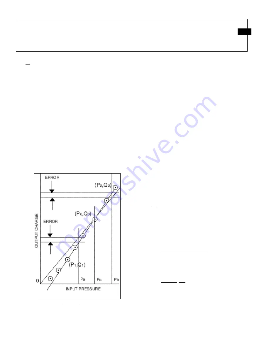
Consider again the calibration graph of a typical
conformal sensor, shown in figure 4.
To calibrate a conformal sensor, the input pressure is
increased in discrete steps from 0 psi to full scale with
the corresponding output recorded at each step. The
information must be taken only once and only with
increasing pressure. A repeat run on the same cartridge
case will not yield the same values as the initial run due
to work hardening of the cartridge case metal.
Figure 4
At the lower pressures, the sensor has very little output
because there is a certain amount of clearance between
the cartridge case and the chamber wall. Obturation of
the cartridge occurs in this region.
However, when obturation is complete, the sensor
output is then linear with pressure from this point up to
maximum rated pressure.
In the past, a common procedure has been to calibrate
the conformal at the expected nominal pressure, deriving
a sensitivity at this point, e.g. point Po, Qo in figure 4.
The sensitivity determined by dividing output Qo by
corresponding pressure input Po, would then yield the
exact result if the input pressure was always exactly Po.
However, should the input pressure change to Pa, it is
clear that the reading would be in error, as shown in Fig.
4, since the actual sensitivity of the instrument is not the
same at Po, as it is at Pa.
A solution to this problem lies in utilization of equation
4.
C
m
y
x
(Eq. 4)
Expressed in terms of sensor transfer parameters, input
pressure and output charge
intercept
(pC/psi)
slope
(pC)
charge
indicated
(psi)
pressure
Indicated
(Eq. 5)
Where the slope of the line is defined as:
psi
pC
P
P
Q
Q
Slope
1
2
1
2
(Eq. 6)
and the intercept is the pressure axis intercept.


