


4
Assembly Instructions
Assembly
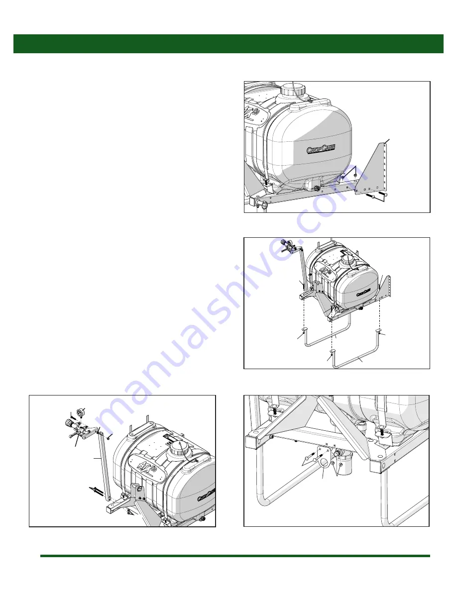
1. Install the control post and control assembly (a) on the
sprayer frame using two 3/8” x 3 3/4” carriage bolts (b) and
two 3/8” flange nuts (c) as shown (Figure 1). Bolt control
assembly (h) to control post (a) using one 3/8” x 2” carriage
bolt (d), a lock washer (e), and a 3/8” flange nut (f). Thread
pressure gauge onto control assembly (g). Threading the
gauge in by hand, using the face of the gauge will cause
damage to it’s internal components. Install the gauge
using the brass mounting base and a wrench, being
careful not to over tighten.
2. The control post will need to be tilted slightly, as shown,
to clear the sprayer tank (Figure 3).
3. Install the boom mounting angles (a) on the sprayer frame
in the upright position using two 3/8” x 3” carriage bolt
(b), and two 3/8” flange nuts (c) for each angle, as shown
(Figure 2).
4. Install the 3pt legs (a) using two 3/8” x 2 3/4” carriage bolts
(b) and two 3/8” flange nuts (c) on the rear of the sprayer
(Figure 3).
5. Use the 3/8” x 3” carriage bolts (d, Figure 3) and two 3/8”
flange nuts (e, Figure 3) to fasten the legs to the front of
the sprayer. These nuts must be removed before bolting
the legs on. Items d and e are already attached to the
frame.
6. Use (2) 1/4” x 2 1/2” flange bolts (a) and two FN14 flange
nuts to bolt T732 (c) to the front of the frame as shown in
figure 4.
Figure 2: Boom mounting angles
Figure 3: 3pt legs
Figure 1: Control post assembly
Figure 4: T732 Installation
a
b
c
b
c
a
d
e
d
e
a
a
b
c
g
a
b
c
h
d
e
f
Содержание CropCare ATX60-3PT-P
Страница 6: ...6 Hose Routing Assembly Instructions 3 4 Suction Hose 3003 6810052 6812052...
Страница 7: ...7 Notes...
Страница 8: ......


