background image


Introduction


3


SmartNode 4900 Quick Start Guide 


Introduction


This Quick Start Guide leads you through the basic steps to set up a new SmartNode and to download a con-
figuration. Please note that this guide does not replace the detailed Software Configuration Guide and the Get-
ting Started Guide on the CD-ROM and available online at 


www.patton.com/voip


.

SmartNodes can be used for a wide variety of IP and voice over IP applications. To support and ease the config-
uration of the SmartNodes configuration templates for the most important applications are available online at 


http://www.patton.com/voip/appnotes.shtml


.

Setting up a new SmartNode consists of the following steps:


1.


Attach the power cable retainer clips to the unit 


2.


Connect a PC to the SmartNode, log in and configure your LAN IP address (see 

page 4

 for details)


3.


Connect the SmartNode to the LAN (see 

page 6

)


4.


Download a configuration example, adapt it to your network, and load it onto the SmartNode (see 

page 7

)


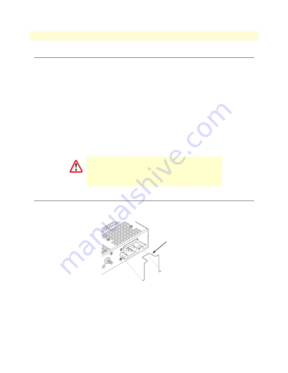
Attaching the cable retainer clips


To secure the power cord, it is necessary to attach the metal retainer clips (if applicable to your model). Squeeze 
the clip and insert into the holes in the screws on either side of the power connector on your unit. The clip will 
pop into place. 


Figure 1. Attaching the cable retainer clips


Note


Refer to the 


Getting Started Guide 


on the CD-ROM or on the Patton 

website for detailed instrauctions about grounding and connecting 
power to your unit. 


For FXO (/JO) models:


 To maintain CE/EMC compliance, 

attach the included snap-on ferrite clamp (Patton P/N 0818S-
02) to the 64/50 pin telco cable (not included but available 
upon request) about four inches away from the FXO box telco 
port connector. 

IMPORTANT

Power cable

retainer clip

VoIPon   www.voipon.co.uk   [email protected]   Tel: +44 (0)1245 808195   Fax: +44 (0)1245 808299 

Содержание SmartNode 4900

Страница 1: ...ort 1 301 975 1007 E mail support patton com WWW www patton com Document Number 13217U7 001 Rev C Part Number 07MSN4900 QS Revised January 13 2010 Start Installation For Quick Start Installation For Q...

Страница 2: ...c tronics assumes no liability for errors that may appear in this document In no event shall Patton Electronics or its employees and associated companies be lia ble for any incidental special indirect...

Страница 3: ...4 for details 3 Connect the SmartNode to the LAN see page 6 4 Download a con guration example adapt it to your network and load it onto the SmartNode see page 7 Attaching the cable retainer clips To...

Страница 4: ...e included black Ethernet cable and RJ45 to DB 9 adapter for this purpose Model 16F 561 Figure 2 Connecting to the PC 2 Open a Terminal connection to the SmartNode Use the Terminal program included wi...

Страница 5: ...1 cfg context ip router 172 16 40 1 ctx ip router 2 Set the IP address and network mask for the each IP interface eth0 for example Note For the examples in this guide a private network 172 16 1 IP add...

Страница 6: ...n guration from a template See Downloading a con guration example adapting it to your network and loading it onto the SmartNode on page 7 for further details For a detailed description of the CLI refe...

Страница 7: ...ration Guide for information on con guring the SmartNode device In this example we assume the TFTP server on the host with the IP address 172 16 1 11 and the con guration named SN cfg in the root dire...

Страница 8: ...mity for English version Produktbezeichnung SmartNode 4900 Die bezeichneten Produkte stimmen in der von uns in Verkehr gebrachten Ausf hrung mit den Vorschriften folgender Richtlinie berein R TTE 1999...

Отзывы: