USERMANUAL
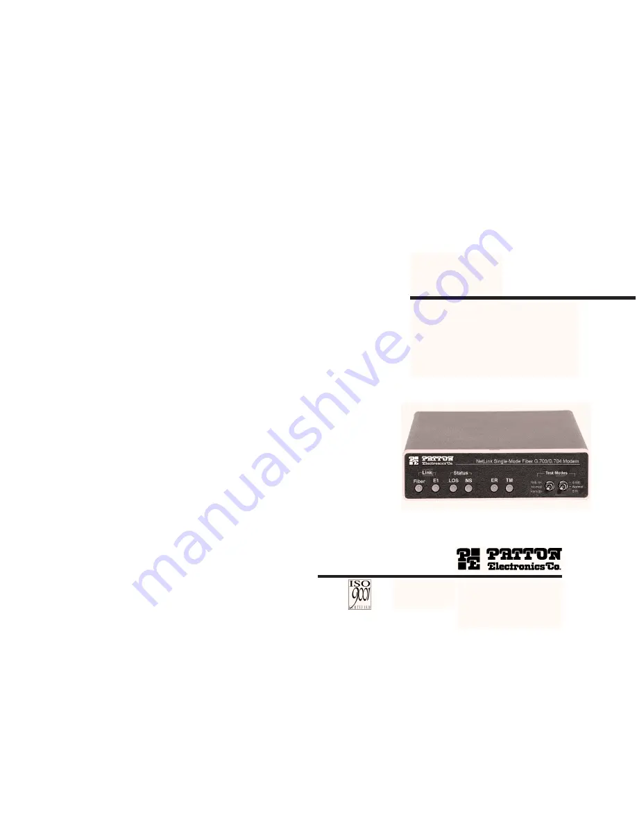
MODEL 1193
Single-Mode Fiber Modemwith Fixed G.703/G.704Interface
Part# 07M1193-UMDoc# 01713U2-001,Rev. CRevised 10/25/06
SALES OFFICE(301)975-1000TECHNICAL SUPPORT(301)975-1007http://www.patton.com
An ISO-9001
Certified
Company
Страница 1: ...3 Single Mode Fiber Modem with Fixed G 703 G 704 Interface Part 07M1193 UM Doc 01713U2 001 Rev C Revised 10 25 06 SALES OFFICE 301 975 1000 TECHNICAL SUPPORT 301 975 1007 http www patton com An ISO 90...
Страница 2: ...ties expressed or implied and the installation or use of this product shall be deemed an acceptance of these terms by the user 1 1 RADIO AND TV INTERFERENCE The Model 1193 generates and uses radio fre...
Страница 3: ...fiber Single mode fiber with max distance 50km 31 miles Two fiber connection options available FC or SC 120 Ohm RJ 48C and 75 Ohm dual coax G 703 G 704 termina tions Clocking options Internal Network...
Страница 4: ...de of the 1193 S1 S2 Setting Description On On Internal Transmit clock generated internally On Off Receive Recover Transmit clock derived from the line Off On Network Transmit clock derived from G 703...
Страница 5: ...e set to OFF 3 1 2 Select RJ 48C or BNC Connectors The Model 1193 is shipped configured for use with a BNC connec tion to the G 703 G 704 Network If your Network connection is using BNC skip this sect...
Страница 6: ...ia dual coaxial cable see Figure 7 below to make the proper connections 4 2 CONNECT THE FIBER INTERFACE The Model 1193 is designed to be connected to another Model 1193 The Model 1193 supports communi...
Страница 7: ...onfigured and installed it should operate transparently This section describes power up LED status monitors and the built in loopback test modes 5 1 POWER UP To apply power to the Model 1193 read Sect...
Страница 8: ...The local loopback test checks the operation of the local Model 1193 and is performed separately on each unit The following section describes how to perform a local loopback test between the Network a...
Страница 9: ...DL test return the front panel switch to NORMAL position The TM LED should turn off on both local and remote units 5 3 3 The V 52 Test Pattern Generator To use the V 52 BER test in conjunction with th...
Страница 10: ...ed NS LED indicates that the sig nal on the fiber side is too weak to be detected ER Flashing red ER LED indicates errors in 511 test pattern TM The yellow TM LED indicates that modem is in a test mod...
Страница 11: ...100 240VAC 5V 5 reg DC 2A Universal Input Adapter 0805EUR European Power Cord CEE 7 A 0805UK United Kingdom Power Cord D 0805US American Power Cord K 0805AUS Australia New Zealand Power Cord C 0805DE...