background image


5


1.3  SERVICE


All warranty and non-warranty repairs must be returned freight prepaid 
and insured to Patton Electronics. All returns must have a Return Materi-
als Authorization number on the outside of the shipping container. This 
number may be obtained from Patton Electronics Technical Service at:

Tel: 


(301) 975-1007


E-mail: 


[email protected]


URL: 


www.patton.com


Note


Packages received without an RMA number will not be 

accepted.


Patton Electronics’ technical staff is also available to answer any ques-
tions that might arise concerning the installation or use of your Model 
1080ARC. Technical Service hours: 


8AM


 to 


5PM EST


Monday


 through 


Friday


.

Содержание 1080ARC

Страница 1: ...DEL 1080ARC Universal Synchronous Asynchronous Short Range Modem Rack Mount Card SALES OFFICE 301 975 1000 TECHNICAL SUPPORT 301 975 1007 Part 07M1080ARC D Doc 072051UD Revised 7 12 01 An ISO 9001 Cer...

Страница 2: ...ngth 12 3 4 Configuration Switch Set S3 13 S3 1 Input Impedance 14 S3 4 Mode Selection 14 S3 5 RS 232 Initiation of Local Loopback Test 14 S3 6 RS 232 Initiation of Remote Loopback Test 15 S3 7 and S3...

Страница 3: ...ndicators 28 Setting Up The Error LED To Test Cable Quality 28 Reading The Test 29 5 2 Antistreaming Error Indicator 29 5 3 Power up 30 5 4 Test Modes 30 Local Analog Loopback LAL 30 Remote Digital Lo...

Страница 4: ...art 15 of the FCC Rules These limits are designed to provide reasonable protection against harmful interfer ence when the equipment is operated in a commercial environment This equipment generates use...

Страница 5: ...iner This number may be obtained from Patton Electronics Technical Service at Tel 301 975 1007 E mail support patton com URL www patton com Note Packages received without an RMA number will not be acc...

Страница 6: ...o point or multipoint Internal external or received loopback clocking Hardware and software flow control support Built in transformer isolation high speed surge protection Bi color LED indicators Swit...

Страница 7: ...52 compliant bit error rate pattern tests and two V 54 test modes The Model 1080ARC is designed to mount in Patton s 2U high 19 rack chassis This 16 card chassis has a switchable 120 240 volt power su...

Страница 8: ...erate transpar ently without need for frequent re configuration 3 1 SWITCH LOCATIONS AND ORIENTATION The Model 1080ARC has three sets of eight switches S1 S2 and S3 which are mounted on the PC board F...

Страница 9: ...n Function Factory Default S1 1 Data Rate On 9 600 bps S1 2 Data Rate Off 9 600 bps S1 3 Data Rate Off 9 600 bps S1 4 Data Rate On 9 600 bps S1 5 Clock Source On Internal S1 6 Clock Source On Internal...

Страница 10: ...tting for switch S1 8 determines whether the carrier is constantly on or controlled by RTS This setting allows for operation in switched carrier multipoint and or hardware handshaking applications see...

Страница 11: ...et switch S2 3 to the ON position then back to the OFF position see Table 8 Table 6 Summary of DIP switch default settings for S2 Position Function Factory Default S2 1 Not Used N A S2 2 2 Wire 4 Wire...

Страница 12: ...nous data rates i e the actual variance from a given frequency level the Model 1080ARC will tolerate see Table 10 S2 7 and S2 8 Word Length Switches S2 7 and S2 8 are set in combination to determine t...

Страница 13: ...hms S3 2 Input Impedance Off 200 Ohms S3 3 Not yet assigned n a S3 4 Mode Selection On Point to Point S3 5 Local Loopback Off Disabled S3 6 Remote Loopback Off Disabled S3 7 Antistream Control Off Dis...

Страница 14: ...setting S3 4 Mode Selection The setting for switch S3 4 allows the user to choose the appropriate set ting for point to point or multipoint applications see Table 15 S3 5 RS 232 Initiation of Local L...

Страница 15: ...17 S3 7 and S3 8 Antistream Control Switches S3 7 and S3 8 are set in combination to determine the timeout period for the Model 1080ARC s antistream control timer see Table 18 Table 17 RS 232 Remote...

Страница 16: ...our different interface options for the Model 1080ARC Figure 3 Model 1080ARC interface card options Prior to installation you will need to examine the rear card that you have selected and ensure that...

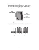
Страница 17: ...RJ 45 rear cards These straps determine various grounding characteristics for the RS 232 and twisted pair lines Figure 4 DB 25 RJ 11 DB 25 RJ 45 strap locations Figure 5 shows the orientation of the...

Страница 18: ...ed from the frame ground see Table 20 DTE Shield Pin 1 FRGND JB3 In the connected closed position this strap links DB 25 pin 1 and frame ground In the open disconnected position pin 1 is lifted from f...

Страница 19: ...J 45 Strap Settings Figure 6 shows strap locations for the Model 1000RCM1D11 RJ 45 RJ 11 and the Model 1000RCM1D45 RJ 45 RJ 45 rear cards These straps determine various grounding characteristics for t...

Страница 20: ...SGND FRGND JB5 This strap pertains to the DTE interface which is a 10 position modular RJ 45 jack In the connected closed position this strap links modular pin 5 Signal Ground and frame ground In the...

Страница 21: ...pera tion when placed on pegs 1 2 Placing the strap on pegs 2 3 is not a valid option when using this rear interface card in conjunction with the Model 1080ARC see Table 26 Table 26 DTE Interface Pin...

Страница 22: ...l 1000R16P rack uses the same mid plane architecture as the modem cards The front card of the power supply slides in from the front and the rear card slides in from the rear They plug into one another...

Страница 23: ...he rack when you install or remove a Model 1080ARC 4 3 WIRING THE MODEL 1080ARC Each of the rear interface cards compatible with the Model 1080ARC has one RS 232 port and one 4 wire twisted pair port...

Страница 24: ...ection of a 2 wire or 4 wire twisted pair circuit between two or more Model 1080ARCs requires a crossover cable as shown in Table 27 Table 28 Table 29 Table 30 and Figure 8 Connection to ground is opt...

Страница 25: ...not sensitive to polarity Figure 8 AT T standard modular color codes Table 29 RJ 11 2 Wire SIGNAL PIN COLOR COLOR PIN SIGNAL XMT 3 Green Green 3 XMT XMT 4 Red Red 4 XMT Table 30 RJ 45 2 Wire SIGNAL PI...

Страница 26: ...ps data rate wire gauge etc Call Patton Technical Sup port for specific distance estimates Figure 9 and Figure 10 show how to wire the one pair and two pair cables properly for a Model 1080ARC star to...

Страница 27: ...st modes 5 1 LED STATUS MONITORS The Model 1080A features six front panel status LEDs that indicate the condition of the modem and communication link Figure 11 shows the front panel location of each L...

Страница 28: ...test mode green Test LED is off the error LED is used to indicate an RTS streaming condition See section 5 2 Antistreaming Error Indicator on page 29 for information on the antistreaming circuitry C...

Страница 29: ...twisted pair is broken Error LED will light red and CD LED will light green on at least one modem Note We cannot guarantee accurate detection if small pieces of flat cable are present in the line bey...

Страница 30: ...anel The V 54 test can also be activated from the RS 232 interface Note V 54 and V 52 test modes on the Model 1080ARC are available for point to point applications only Local Analog Loopback LAL The L...

Страница 31: ...equipment If you still have errors call Technical Support at 301 975 1007 Remote Digital Loopback RDL The Remote Digital Loopback RDL test checks the performance of both the local and remote Model 108...

Страница 32: ...ly The Model 1080ARC s V 52 BER test can be used independent of the V 54 loopback tests This requires two operators one to initiate and monitor the test at both the local and the remote Model 1080ARC...

Страница 33: ...ected Clocking Internal external or receive recover Controls Carrier constantly ON or controlled by RTS RTS CTS delay set to no delay 7 or 53 ms Applications Point to point or multi point Indicators B...

Страница 34: ...ur catalog Resistance will also affect distance but not functionality Wire should be 26 AWG or larger smaller AWG Patton products are designed to withstand normal environmental noise and conditions ho...

Страница 35: ...ion of the proper SRM for an application is critical to maintaining Customer Satisfaction and should be taken seriously Certain models are better suited for particular applications and environments th...

Страница 36: ...1000RPEM DC DC Rear Power Entry Module 1000RPSM 48A 48V Front Power Supply Module 0805US American Power Cord 0805EUR European Power Cord CEE 7 0805EURP Europlug Power Cord CEE 7 16 0805UK United Kingd...

Страница 37: ...080ARC 3 RD Receive Data From 1080ARC From 1080ARC Receive Clock 17 4 RTS Request to Send To 1080ARC To 1080ARC Analog Loop 18 5 CTS Clear to Send From 1080ARC 6 DSR Data Set Ready From 1080ARC 7 SG S...

Страница 38: ..._________________ _________________________________________________________ _________________________________________________________ _________________________________________________________ ________...

Страница 39: ..._________________ _________________________________________________________ _________________________________________________________ _________________________________________________________ ________...

Страница 40: ...____________________________________________ _________________________________________________________ _________________________________________________________ _______________________________________...

Отзывы: