20 | P a g e
PATON
®
VDI PROFESSIONAL SERIES DC MMA/TIG/MIG/MAG
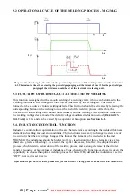
5.2 OPERATIONAL CYCLE OF THE WELDING PROCESS - MIG/MAG
The procedure for changing the values of the operational parameters of the welding unit is described in Section
6.1. The instant of time t1 for starting the preweld gas purging and the instant of time t2 for the post weld gas
purging of the weld area should be set at the electrode wire feeding unit.
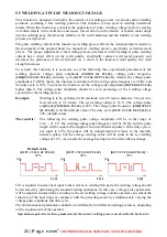
5.3 FUNCTION OF BURNING OUT AT THE END OF WELDING
This function is designed for the smooth welding of a welding crater, which can be formed in the
welding pool due to electromagnetic blow forces generated by the welding arc. The crater so
formed can be a source of future welding defects. This function should be activated by releasing the
corresponding button on the welding torch at the end of the welding process. After this, the
movement of the welding torch should be terminated, and the welding crater should be welded in
the welding voltage decay mode. The default voltage modulated reduction period
[TIME DOWN
VOLTAGE]
is 1.0 s and can be varied by the operator at his option
(see Section 6 .1).
5.4. INDUCTANCE CONTROL FUNCTION
Inductance control allows optimization of the arc characteristics according to the welded thickness
element and welding method and conditions. This function is necessary to change the slew rate of
the current when the arc voltage changes. The thinner the element to be welded with the met
MIG/MAG the inductance should be higher (soft arc - less fusion), for thick elements vice versa
(hard arc - greater embedding). As a result, the spatter decreases, but affects the droplet transfer
process, which leads to a slowdown of the welding process and a strong decrease in the droplet
transfer frequency at high values of inductance. Thus, changing this function, each user is given the
opportunity to choose the optimal welding process for himself. By default, the inductance is set to
“OFF”, that is, it is set to zero.
Operations required to set these parameters for the current welding process are described in Section 6.1.
t, s
t, s
t, s
I (A)
Содержание VDI 160 PRO
Страница 1: ......


