Service Manual
DS 350 Modular
© PAT
Rev. - 12/18/00 // CSH.
190118_-.DOC
28
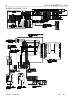
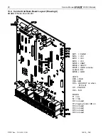
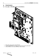
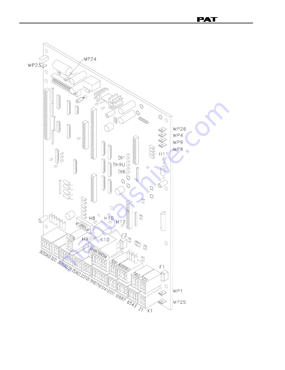
13.4 Central Unit Main Board Layout (Drawing 4)
BOARD P/N 024-352-300-001
MP1 = KGND
MP4 = +5V
MP8 = +9V
MP9 = +6V
MP23 -= VBAT
MP24 -= +BATT
MP25 -= +UBS console,
sensors, DI’s
MP26 -= GND
LED’S
H08 - LOAD
H09 - A2B
H10 – LOCKOUT on when
K10 is lit
H11 - POWER
H12 – TxD
FUSES
F1 = 4A
F2 = 10A
DI 1 not used
D1 2 rigging mode +UB on
DI 3 not used
DI 4 not used
DI 5 not used
DI 6 not used
Содержание DS 350
Страница 2: ......
Страница 4: ......
Страница 6: ......
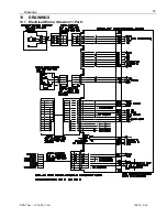
Страница 29: ...Drawings PAT Rev 12 18 00 CSH 190118_ DOC 23 13 DRAWINGS 13 1 Electrical Wiring Drawing 1 Part 1 ...
Страница 30: ...Service Manual DS 350 Modular PAT Rev 12 18 00 CSH 190118_ DOC 24 Electrical Wiring Drawing 1 Part 2 ...
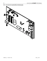
Страница 36: ...Service Manual DS 350 Modular PAT Rev 12 18 00 CSH 190118_ DOC 30 13 6 Console Connection Board Drawing 6 ...


