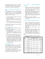
contact alignment. This alignment will be
discussed later under blade entry (step 6).
Step 5—Mount Switches
Assemble the switches on the supporting
structure in accordance with the positions shown
on the installation drawing. The switches
should be mounted level and parallel with each
other. In case of a warped structure, shimming
under the switch bases may be required.
Step 6—Switch Blade Adjustment
When looking down on the switch rotating
insulator column, rotation of the column is
clockwise to open the switch and
counterclockwise to close. First, make sure that
stop bolts (Fig. 13) at base of rotating insulators
do not prevent switch from traveling to the
complete open and closed positions, then check
each pole unit for the following items:
Blade Entry
—Lower the blades slowly to the
closed position to see if blade contact enters the
jaw in a central position. If it does not, loosen
the hinge assembly mounting bolts on stationary
insulator stack and with blade just out of the
jaw, shift blade into alignment and tighten hinge
assembly mounting bolts. Should this fail to
give proper blade entry, the jaw insulator stack
should be shimmed or adjusted to suit. When
central entry is achieved, rotate the blade into
contact and tighten jaw base mounting bolts.
Also make certain the jaw fingers are nearly
centered on the blade end contact. If it is
expected that the conductors to
be attached to
the switch jaw will impose an appreciable
horizontal force, it is recommended that the jaw
insulator column be adjusted so that the jaw
fingers are slightly off center on the blade
contact, in a direction toward the hinge end. The
blade must rotate on opening and closing to
relieve the jaw contact pressure
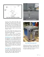
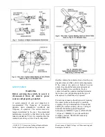
Blade Contact Angle
—(Fig. 4) The allowable
difference in elevation from one side of the
blade contact to the other (dimension X) is 1/16”
for each 1” of contact width. Example: If
contact width (A) is 4 1/2”, then dimension (X)
can be as much as 9/32” and still be within the
plus or minus 4 degree tolerance.
4|
P a g e
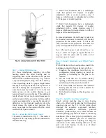
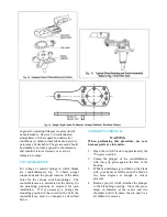
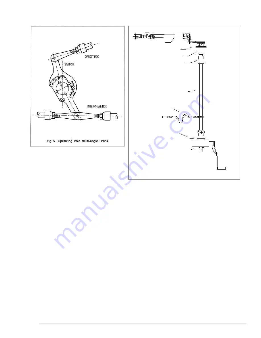
Adjustable Clevis
Connecting Link
Offset Bearing Rod
Rotor Bearing
Coupling
Operating
Pipe
Flexible Ground
Strap
Manual
Worm-Gear
Operator
Fig. 5a Manual Worm Gear Operating Mechanism
Содержание TTR6
Страница 1: ...IB TTR6 B May 2012 ...
Страница 6: ...5 P a g e ...

