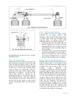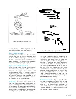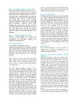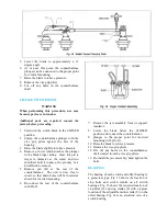
horn makes contact with the rear surface
(corona-protected surface) of the corona ball.
Note: Always check switch operation mechanism
drawing for type of arcing horns supplied.
Step 14—Installation of Corona Rings and
Balls
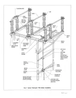
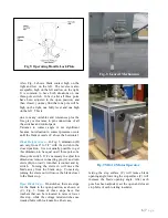
Corona rings and balls, when supplied, should
be installed as shown on the single-pole
drawings. Prepare areas where ring supports
contact switch parts per instructions for
aluminum connections at right.
1.
169 kV switches and below do not require
corona rings or ball.
2.
242 kV switches use corona rings at the jaw
end and a small ball on each end of the
blade.
3.
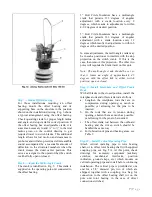
362 kV switches and above use rings at both
ends and a large ball on the end of the blade.
After these are installed, the switches should
now be ready for service.
Step 15—Final Checks
The completed 3-pole installation should be
checked for the following:
1.
In the open position, the blades should stand
essentially vertical.
2.
In closing, blades should make central entry
into their jaws at approximately the same
time.
3.
In the closed position, all blades must be in
full contact and horizontal within tolerances.
4.
In opening, the blades should rotate to
relieve the jaw contact pressure. (If the blade
remains flat, the blade beaver tail will
engage the stops formed on the jaw fingers
and further operating effort can result in
mechanical damage.) Recheck base crank
orientation per step 4.
Terminal Connections
The aluminum surface of the terminal
connection provides for easy current transfer.
Notice: In cases where a copper conductor is
used, bolt a tinned terminal clamp (if available)
to the aluminum switch terminal pad.
If a non-tinned terminal clamp is used, apply a
liberal amount of electrical joint grease at the
joint and all over the pad of the fitting.
To connect aluminum-to-aluminum
terminals:
1.
Clean all contact surfaces of conductors and
fittings using a stiff wire brush to remove
heavy oxide coatings until the aluminum
finish is visible and restored.
2.
Coat these now clean contact areas with a
liberal amount of corrosion inhibitor such as
NO-OX-ID”A Special” or No. 2 EJC.
3.
Abrade the contact surface through the
corrosion inhibitor again using the stiff wire
brush.
Notice: Do not remove the compound
.
4.
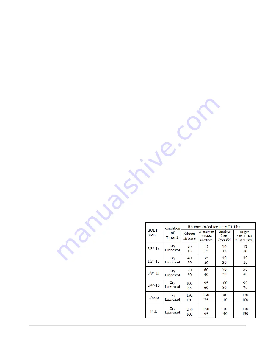
Connect the terminals and torque the bolts
as per Table 1.
To connect copper-to-aluminum terminals:
1.
Except for plated surfaces, clean all contact
surfaces of conductors and fittings using a
stiff wire brush to remove heavy oxide
coatings until the aluminum finish is visible
and restored.
2.
Prepare any bare copper surfaces in the
usual manner.
3.
Coat these now clean contact areas with a
liberal amount of corrosion inhibitor such as
NO-OX-ID “A Special” or no. 2 EJC.
4.
Abrade the contact surface through the
corrosion inhibitor using a stiff wire brush.
Notice: Do not remove the electrical joint
grease
.
5.
Connect the terminals and torque the bolts
as per Table 1.
9 |
P a g e
Содержание TTR6
Страница 1: ...IB TTR6 B May 2012 ...
Страница 6: ...5 P a g e ...

