®
Set Up the Hardware
PS
-
3216
5
013-15734A
use the <Select Measurement> menu to pick a
measurement to be shown.
•
Select Record to begin collecting data.
Troubleshooting the Wireless Load Cell
•
If the Wireless Load Cell loses Bluetooth connection
and will not reconnect, try cycling the ON button.
Press and briefly
hold
the button until the status
LEDs blink in sequence, and then release the
button. Start the sensor in the usual way.
•
If the sensor stops communicating with the
computer software or tablet application, try
restarting the software or application. If the problem
remains, press and hold the ON button for 10
seconds and then release. Start the sensor in the
usual way.
•
Turn Bluetooth off and then turn it back on. Retry.
Set Up the Hardware
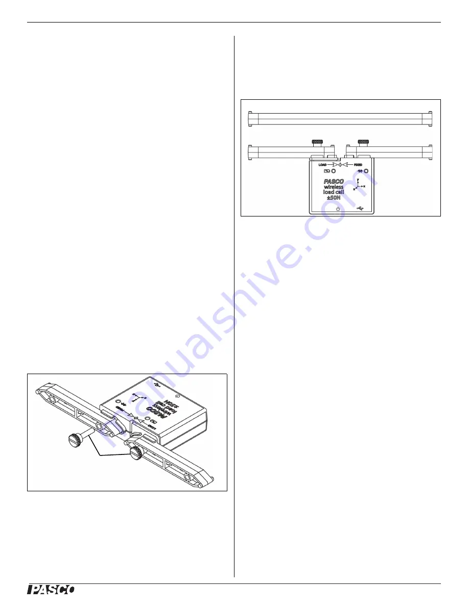
Connecting Structure Members
The Wireless Load Cell is designed to work with the
PASCO Structures Systems, such as the ME-3581
Building Better Bridges Kit. The sensor can measure
compression and tension forces in any member of the
PASCO Structures Systems. Use thumbscrews to
mount I-Beams or other items from the Structures
Systems to the Wireless Load Cell
Adding Load Cells
To measure the tension and compression forces in indi
-
vidual members of a PASCO Structure, replace a beam
with two shorter beams and the Wireless Load Cell.
A Wireless Load Cell combined with two #2 beams is the
same length as a #4 beam.
#5 beam = load cell + two #3 beams
#4 beam = load cell + two #2 beams
#3 beam = load cell + two #1 beams
Calibration of Wireless Load Cells
Wireless Load cells are factory calibrated; however, you
can recalibrate them in software. See the documentation
for your software for instructions.
When calibrating a Wireless Load Cell, it is necessary to
apply a known load. Assemble the fixture shown in the
figure below to support the Wireless Load Cell. Hold or
#2 Beam
I-Beam
Thumbscrews
#2 Beam
#4 Beam
#2 Beam


