background image

Model No.ME-8236

 Operation

7

012-13762C

Finishing Step

Click “Finish” to store the calibration as part of the Cap-
stone file.

NOTE: The “Calibration” window goes back to Step One. 
When you click “Next”, the “Choose Calibration Action” 
window (Step Two) will show a menu of the stored calibra-
tion(s). Click “Use Calibration” to select a specific stored 
calibration.

Click the “Calibration” icon in the Tools palette to close 
the “Calibration” window. Save the Capstone file for 
future use.

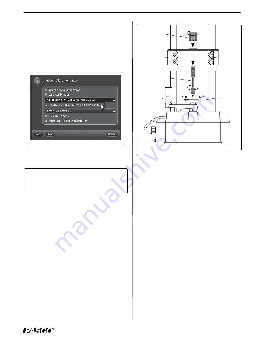
Mount a Tensile Sample

Select a tensile sample to mount onto the Materials Testing 
Machine. Put the end of the sample with the short threaded 
section into the threaded hole in the top of the load cell. 
Screw in the sample until the top edge of the short threaded 
section is flush with the top of the load cell. 

Lower the load bar so that the longer threaded section of the 
sample goes up through the hole in the center of the load bar. 
Adjust the load bar until the bottom edge of the longer 
threaded section is flush with the bottom of the load bar. 
While holding the tensile sample so it does not turn, screw 
the sample nut onto the longer threaded section until the 
sample is held tightly in place.

Attach the Safety Shields

Attach the Velcro® hook material on the two safety shields 
to the Velcro® loop material on the front and back of the 
Load Bar. Adjust the position of the shields so that they will 
block any fragments that may come from the sample. 

Record Data

Prepare PASCO Capstone software to record data. (If there is 
a stored calibration file that is to be used, select it in the 
“Calibration” window.)

Start data recording in the software. Turn the crank in a 
clockwise direction to apply a tension force to the tensile 
sample. Observe the graph display of force and position. 
(Note that the default for the Materials Testing Machine in 
the software shows force and position as ‘negative’ when a 
tension force is applied.)

When the sample breaks, or is stretched the maximum 
amount, stop data recording. 

Materials Bending Accessory (ME-8237)

The Materials Bending Accessory includes a plunger, a 
adjustable support anvils, and a small hex key (allen 
wrench). The plunger is mounted on the bottom of the load 
bar using the sample nut. The base for the adjustable anvils 
is screwed onto the top of the load cell. 

The spacing between the two triangular support anvils can be 
adjusted. Use the hex key to loosen the screws holding the 
anvils and slide them closer together or farther apart. Tighten 
the screws securely.

Figure: Use Calibration

NOTE

: Information about the calibration proce-

dure is included in the Appendix of this manual 
and in the Experiment Guide that can be down-
loaded from the PASCO web page.

Load Bar 

Sample 

Nut

Tensile 

Sample

Crank 

Handle

Load 

Cell

Figure: Mount Tensile Sample

Loop 

Material 

for Safety 

Shield

Load Bar 

(crosshead)

Содержание ME-8230

Страница 1: ...ad Tensile Samples 60 Sensor Cable Load Bar Round Nut Velcro Loop Material Safety Shield 2 Velcro Hook Material WARNING Provide proper eye protection when using the Materials Testing Machine or its Accessories Operate the Materials Testing Machine behind protective Safety Shields Crankshaft Base USB Link Items from the ME 8230 Materials Testing System Materials Testing Machine ...

Страница 2: ... or in compression The load bar round nut is used to connect one end of a tensile sample to the load bar for example or can be used to attach an accessory or adapter to the load bar The safety shields attach to the Velcro loop material on the front and back of the load bar Materials Testing System The Materials Testing System ME 8230 consists of the Materials Testing Machine plus a PASPORT interfa...

Страница 3: ...ounting the Materials Testing Machine firmly to a sturdy support calibrating the Machine mounting the item to be tested onto the Materials Testing Machine connecting the Materials Testing Machine to an interface for data recording and then turning the crank to apply tension stretching compression squeezing bend ing or shearing cutting forces to the test item Secure the Materials Testing Machine Th...

Страница 4: ... will block any fragments that may come from the calibration rod in case it accidentally breaks Prepare to Record Calibration Data Connect the plug on the sensor cable into a PASPORT inter face such as the USB Link Connect the interface to a USB port on a computer Start the PASCO Capstone software Prepare to use the soft ware to calibrate the Material Testing Machine Optional Change Sign Note that...

Страница 5: ...e described in the appendix Step Three Click Next to show the illustration in Step Three Install the calibration rod In addition to the illustration a Graph display of Position m versus Force N opens A Digits display of Force N is part of the Graph display Step Four Click Next to open Step Four Record a smooth data run Figure Step One Calibration window NOTE Detailed information about the calibrat...

Страница 6: ...nomial Fit NOTE By default the Show Curve Fit Editor window is open in the Polynomial Fit window If the message Curve fit was successful is shown click Next to open Step Six Name the calibration NOTE If the curve fit was not successful use trial and change in the Curve Fit Editor to adjust the coef ficients until the curve fit is successful Click Update Fit to determine if the new coefficients mad...

Страница 7: ...ck of the Load Bar Adjust the position of the shields so that they will block any fragments that may come from the sample Record Data Prepare PASCO Capstone software to record data If there is a stored calibration file that is to be used select it in the Calibration window Start data recording in the software Turn the crank in a clockwise direction to apply a tension force to the tensile sample Ob...

Страница 8: ...nto the load cell Put the threaded section of the other clamp up through the hole in the load bar and use the sample nut to hold the upper clamp NOTE Do not completely tighten the sample nut yet Carefully place one end of a coupon between the jaws of the bottom clamp While holding the moveable jaw to keep it aligned with the fixed jaw use the tee handle and socket to tighten the hex nut CAUTION Ea...

Страница 9: ...sample Use a sample that is long enough so that it extends about 1 4 6 mm beyond the front and back pieces Doing this makes it easier to remove the sample remnants from the accessory after the test Adjust the position of the load bar so that it rests on the top surface of the front piece Attach the Safety Shields Attach the Velcro hook material on the two safety shields to the Velcro loop material...

Страница 10: ... Use the included hex key to remove the screws that hold the two parts of the clamp together Put the ends of a structures beam such as a 3 I Beam into one part of each clamp and then use the screws to reattach the other part of each clamp Screw the clamp with the short threaded end into the top of the load cell and put the other clamp through the hole in the load bar Use the sample nut to secure t...

Страница 11: ... their laborato ries and classrooms and are not sold for profit Reproduction under any other circumstances without the written consent of PASCO sci entific is prohibited Trademarks PASCO PASCO Capstone PASPORT SPARK Science Learning System SPARK SLS and SPARKvue are trademarks or registered trademarks of PASCO sci entific in the United States and or in other countries For more infor mation visit w...

Страница 12: ...he Machine Mounting the Calibration Rod To mount the calibration rod for tension screw the short threaded end of the rod into the top of the load cell Lower the load bar until the threaded part at the top of the calibration rod goes through the hole in the load bar Screw the load bar round nut onto the top of the calibration rod To mount the calibration rod for compression screw the short threaded...

Страница 13: ...he icon for the Materials Testing System is linked to the icon for the interface Step One In the software select the Calibration icon in the Tools palette to open Calibration window There are two choices for the type of measurement that can be calibrated The default choice is Materials Testing System Compliance Calibration Use this choice in most cases The other choice is Materials Testing System ...

Страница 14: ...ect an existing calibration Menu list of existing calibrations Import Calibration From Sensor Use this to import a calibra tion that has been stored in the sensor Menu list of calibrations shored in the sensor Use Raw Values Display voltages for force and position Manage Existing Calibration Delete Calibration Rename Calibration or Save Calibration in Sensor NOTE Up to four calibrations can be sto...

Страница 15: ...ll the calibration rod In addition to the illustration a Graph display of Position m versus Force N opens A Digits display of Force N is overlaid on the Graph display Figure Step Three Install the calibration Figure Calibration Graph and Digits Displays Position m Force N Digits display of Force N Tool bar ...

Страница 16: ...the crank counter clockwise and watch the Digits display Reduce the force to between 10 N and 20 N try not to let the force go to zero 6 Start turning the crank clockwise again to increase the force on the calibration rod as before If the second plot tracks on top of the first plot slowly turn the crank counter clockwise until the force on the Digits display is between 10 and 20 N Then carefully i...

Страница 17: ... to increase the number of terms in the polyno mial Click 1 to decrease the number of terms in the polynomial Current Value This column shows the values calculated automatically by the curve fit algorithm The A value is the coefficient for the zeroth order term the B value is the coefficient for the First order term and so on MSE This is an abbreviation for Mean Squared Error It is one way to quan...

Страница 18: ...ration window click the Calibra tion icon in the Tools palette From the File menu save the Capstone file for future use More Help See the Online Help System for the PASCO Capstone software Contact PASCO Technical Support Figure Use Calibration Figure Save Experiment As ...

Отзывы: