Instruction Manual
012
-
16515A
800-772-8700
www.pasco.com
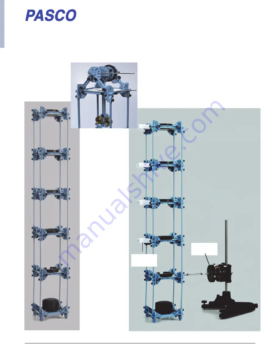
Shaking Tower Kit (ME
7018)
Included in the
Shaking Tower Experiment (EX-5555)
Mechanical
Wave Driver
Wireless
Load Cell
Damping Pendulum Structure
Tower Fifth Floor Structure
Страница 1: ...nual 012 16515A 800 772 8700 www pasco com Shaking Tower Kit ME 7018 Included in the Shaking Tower Experiment EX 5555 Mechanical Wave Driver Wireless Load Cell Damping Pendulum Structure Tower Fifth F...
Страница 2: ...ver Page shows the Shaking Tower Kit ME 7018 on the left side and the Shaking Tower Experiment EX 5555 on the right side The inset in the middle shows the Damping Pendulum Structure which fits on top...
Страница 3: ...e 1 12 Foam Floor 5 4 Nylon Spacer 2 13 Flat F4 Beams 20 5 4 I Beams 1 14 Flat Round Connector 4 6 3 I Beams 24 15 Full Round Connector 5 7 2 I Beams 8 16 Sliding Connector 1 8 1 I Beams 10 17 Half Ro...
Страница 4: ...s the additional equipment needed to shake the tower at various frequencies and to measure the force of the shaking at each floor Shaking Tower Kit Construction There are four parts to the Shaking Tow...
Страница 5: ...the top vertical slot on a Full Round Connector Attach the beam using the Truss Set Screw 5 Repeat the process to attach the other Flat F4 Beams to the other Full Round Connectors using Truss Set Scre...
Страница 6: ...nectors Make sure that the cross bar on the 3 I Beam faces out ward Step Two Place the Foam Floor between the Half Round Connectors with one edge of the floor in the back of the 3 I Beam 3 I Beams 4 T...
Страница 7: ...ound Connectors around the Foam Floor using Truss Set Screws as shown Notice that the cross bar on each 3 I Beam faces outward Build More Floors Use the same process to build four more floors for a to...
Страница 8: ...four Flat 4 Beams to the Second Floor Use the same process to add the Third Floor to the Fourth Floor and the Fifth Floor to the Fourth Floor NOTE do not add any Flat F4 Beams to the Fifth Floor ME 75...
Страница 9: ...xle as the axle is put into the supports Part One Supports for Axle Step One Attach a 2 I Beam to the forty five degree angle slot on each of the Half Round Connectors on the Fifth Floor as shown Note...
Страница 10: ...ird put the Full Round Connector on the Axle with the right angle part pointing as shown in the diagram Step Two Assemble the Pen dulum and attach it to the Axle Attach a Flat Round Connector to one e...
Страница 11: ...es good con tact with the Axle Step Four Mount the Sliding Connector at the middle of one of the 2 I Beams as shown When the Shaking Tower Kit is shaking the Damping Pendulum is damped by adjusting ho...
Страница 12: ...s the Shaking Tower Kit ME 7018 and the follow ing additional items Required but not included 850 Universal Interface UI 5000 PASCO Capstone Software The inset photograph to the right shows the Shakin...
Страница 13: ...Kit are available separately However the items are included in other PASCO products Check the PASCO catalog or the web site at www pasco com to find out what is included in each of the PASCO products...