www.parweld.com
9
Fig 1
Fig 2
6.4 MIG Welding Preparing the Machine
1.
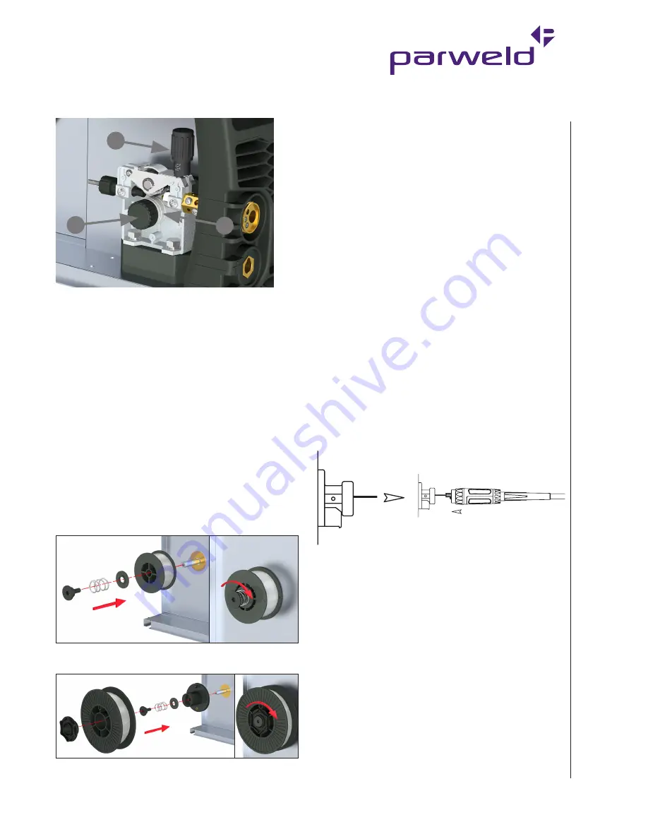
Open the Wire Drive Compartment Door by lifting the 2 finger
catches on the side panel.
2. Release the pressure on the idle roll by swinging the adjustable
pressure arm down towards the front of the machine. Lift the idle
roll assembly and allow it to sit in an upright position.
3. Unscrew the plastic knob retaining the lower grooved feed roll and
slide off the feed roll.
4. Ensure the wire size marked on the side of the feed roll matches
the wire size to be used.
5. Replace the drive in reverse of the above procedure ensuring the
wire size to be used is marked on the outward facing side of the
roller as it is refitted.
Note: Be sure that the torch liner and contact tip are also sized
to match the selected wire size.
Welding Wire Installation
1. Set the spool holder for 100mm or 200mm spool.
2. Position the wire spool so that it will rotate in a direction when
feeding so as to be de-reeled from the bottom of the coil.
100mm (4in.
)
200mm (8in.) 300mm (12in.)
Note: There is a friction brake on the reel hub assembly to
prevent the wire spool over running when welding stops;
ensure this is slackened to the minimum setting. It can be
adjusted by means of the nut visible when the plastic hand nut
is removed.
1. Turn the Spool until the free end of the electrode is accessible.
While securely holding the electrode, cut off the bent end and
straighten the first six inches. (If the electrode is not properly
straightened, it may not feed properly through the wire drive
system). Manually feed the wire from the wire reel and through the
wire guide and then over the top of the wire feed roller (ensure the
pressure arm is in its raised position).
2. Continue to feed the wire through the outlet guide until 20mm of
wire is protruding from the front of the machine torch connector.
3. Reposition the adjustable pressure arm to its original position to
apply pressure. Adjust pressure as necessary.
Note: The pressure arm should be adjusted in order to give
the minimum amount of pressure on the wire to allow reliable
feeding.
MIG Torch Installation
Your Parweld MIG/MAG Welding Torch has been supplied ready to
weld. It has been supplied with the standard consumables denoted
in the product brochure.
To connect the torch to the power source:
1. Remove the tip adaptor and contact tip
2. Inch the wire from the exit of the wire guide on the feed unit as
Figure 1. Ensure that it does not short out on any machine panels.
3. Carefully slide the electrode wire into the torch liner and slowly
locate the torch gun plug body into the feed unit central connector
and tighten the gun plug nut as Figure 2
Note: To aid the initial location of a new torch and to prevent
damage to the gas nipple O-Ring a very light application of
grease to the O-Ring is beneficial.
4. Keeping the torch as straight as possible, use the power source
inch facility or torch trigger to feed the electrode wire 50mm
from the end of the liner conduit.
5.
Once the electrode wire has stopped, refit the tip adaptor,
diffuser, contact tip and gas nozzle.
6. Trim the electrode wire to within 5mm of the face of the nozzle;
this will facilitate jolt free arc initiation.
Note: Check that drive rolls, and torch parts are correct for the
wire size and type being used.
7. The optimum idle roll pressure varies with type of wire, wire
diameter, surface conditions, lubrication and hardness. As a
general rule, hard wires may require greater pressure, and soft
or aluminium wire, may require less pressure than the factory
setting. The optimum idle roll setting can be determined as
detailed on the following page.
4
2
3
Содержание XTM 201Di
Страница 1: ...OPERATOR MANUAL ISSUE 1 XTM 201Di...
Страница 21: ...www parweld com 21...
Страница 22: ...www parweld com 22...
Страница 23: ...www parweld com 23...


