30
GB
• Do not heat the batteries!
• Do not carry out any welding or solder
-
ing work directly on the batteries!
• Do not take the batteries apart!
• Do not deform the batteries!
• Do not throw the batteries into fire!
• Store the batteries out of the reach of
children.
• Do not allow children to replace the
batteries without supervision!
• Do not store the batteries close to a fire,
cookers or other sources of heat. Do not
place the battery in direct sunlight and
do not use or store it in motor vehicles
in hot weather.
• Store used batteries in the original
packaging and keep them away
from metal objects. Do not mix (up)
unpacked batteries! Otherwise this
may cause the battery to short-circuit,
resulting in damage, burns or even the
danger of fire.
• Remove batteries from the device if this
is not going to be used for a prolonged
period, unless it is to be used in emer
-
gencies!
• NEVER touch batteries which have
leaked without appropriate protection.
If the leaked liquid comes into contact
with the skin, you should rinse off this
area of the skin immediately under run-
ning water. Make sure at all events that
your eyes and mouth do not come into
contact with the liquid. If they do, seek
medical advice immediately.
• Clean the battery contacts and the
equivalent contacts in the device before
inserting the batteries.
Assembly
The bench drill is supplied disassembled.
Clean the column tube (6), baseplate (9),
drilling bench (12), vice (13) and the drill
chuck (21) beforehand, with a dry cloth.
1. Place the column tube (6) on the base-
plate (9).
The red marking at the base of the
column tube (6) and the recess in the
baseplate (9) must line up.
Bolt the column tube (6) to the baseplate
(9) with the three assembly srews (8)
(size 13 mm) supplied. Tighten the as-
sembly srews (8) moderately tight so that
the threads in the baseplate (9) do not
strip.
2. Place the drilling bench (12) on the
column tube (6). Push the drilling bench
(12) into a lower position. Use the lock-
ing handle (7) to fix the drilling bench
(12) in a lower position.
B
3. Place the vice (13) on the drilling
bench (12). Screw it firmly onto
the drilling bench (12) by means
of the enclosed assembly screws
(11) (size 17 mm) together with
the washer and the lock washer
in the order as shown.
The two assembly screws (11)
should be positioned diagonally
opposite each other.
C
4. Place the motor unit (5) on the
column tube (6). Secure the mo-
tor unit (5) with the two clamping
screws (16) on the side using the
enclosed Allen key (31).
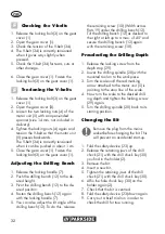
5. Bolt the three drill lifting arms
(22) into the spindle guide (25).
Tighten the three hole lifting
arms with a spanner (Width
across flats 6).
6. Release the clamping screw (29)
from the depth stop (28).
7. Mount the laser on the motor unit
(5) using the fixing screw (33).
Содержание PTBM 400 B1
Страница 3: ...1 3 15 14 16 20 25 5 6 9 30 31 26 24 8 10 12 19 18 32 17 23 21 22 11 13 7 2 4 28 27 29 25 26 27...
Страница 4: ...33 11 20 21 6 23 31 5 16X 13 12 5 19...
Страница 127: ...127 BG 1 5 mm 13 mm 16 16 3 2 x 1 5 V AAA 5x 2x 4x 2x A 1 2 3 4 5 6 7...
Страница 129: ...129 BG 2...
Страница 130: ...130 BG U min mm mm 3 3 4 5 8 6 8 4 5 6 7 8 9 10 10 900 600 2650 1800 1300 1 a...
Страница 131: ...131 BG 2 a e 3 a...
Страница 132: ...132 BG 4 a...
Страница 133: ...133 BG 5 a...
Страница 134: ...134 BG 2 25 6 9 12 13 21...
Страница 138: ...138 BG 1 2 3 21 4 5 6 G 1 2 32 3 18 1 2 17 3 4 17 3 17 4 17...
Страница 139: ...139 BG 8 0 mm 23 1 27 1 26 24 27 14...
Страница 140: ...140 BG 5 9 1...
Страница 142: ...142 BG 27 26 5 4 21 34 34 3 II...
Страница 143: ...143 BG IAN 499273_2204 3...
Страница 144: ...144 BG BG 0800 12220 info kaufland bg IAN 499273_2204 20 63762 33 3 II III...
Страница 154: ...34 36 35 37 3 1 4 5 32 18 6 17...
Страница 155: ......

