Remote’s Features
The HTm (Hand
T r a n s m i t t e r )
remote offers an
array of features
uni qu e in th e
industry. In this
s e c t i o n w e
cover some of
these features.
Toggle vs. Discrete Com-
mands
Toggle commands instruct the
barrier to alternately go up and
go down. This is the standard
configuration for the barrier and
the HTm.
Toggle commands are a simple
and effective way to control the
barrier when it is in line of sight.
You know that if the barrier is
down and you send a command,
the barrier will go up, and vice
versa.
There are applications where
Discrete commands are pre-
ferred. The commands are Up
and Down. If one sends an Up
command and the barrier is up,
the command will be ignored.
Likewise, when the barrier is
down, a Down command will be
ignored.
Discrete commands are available
when using the PK250 long-
range transmitter.
1 or 2 Button Code?
The HTm is shipped in the mode
where only one button is required
to be pressed. For applications
where more than 3 adjacent bar-
riers need to be controlled, the
HTm can be set to a two-button
mode. Up to 9 adjacent barriers
can be individually controlled. A
command is sent only after the
2nd button was pressed (e.g.
button 2 then button 1).
To program the HTm remote to
the 2-button mode, or to return it
to its 1-botton mode, see page 6.
Pairing
Paring is a procedure whereby a
remote is added to the list of de-
vices that are authorized to con-
trol the barrier. It is similar to the
procedure used to pair your
Smartphone with your car for
hands-free operation.
Why 3 buttons?
Each button on the HTm remote
control generates an individual
code. That allows one remote to
control 3 individual MySpot 500.
The HTm also supports a 2-
button mode of operation. In the
2-button mode, 9 MySpot barri-
ers can be controlled individually
.
RESET
Reset is achieved by momentarily
removing power from the electronics
in the barrier unit.
1.
Follow the steps to gain access
to the battery holder (page 11)
2.
Pull out the battery closest to
you, and reinsert it 5 seconds
later.
3.
After the power has been re-
stored to the unit, watch the
green and red LEDs in the front
of the unit just to the left of the
“S” in “RESERVED”.
4.
The sequence of light flashes
identifies the software revision
level. Revision 1.4.1 will flash
green once, red 4 times followed
by green 1 time. This is followed
by 10” of no activity, then 3 quick
red flashes indicating that the
unit is ready to respond.
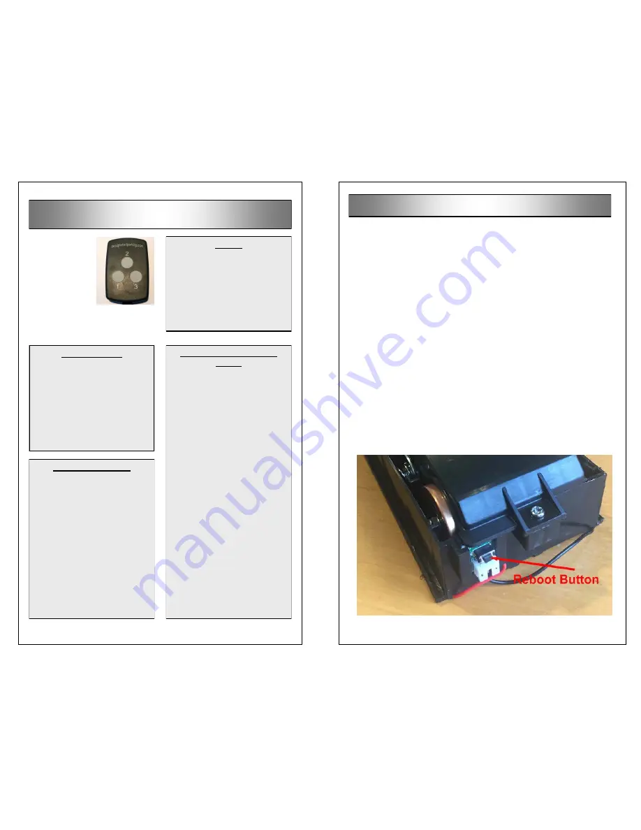
REBOOT
1.
Follow the steps to gain access
the battery holder (page 11)
2.
Pull the battery holder as far as it
will go, exposing all 5 battery
cells.
3.
Reach behind the wall of the
holder. You will feel a push
switch. Push the switch towards
you and hold it for 7 seconds,
then release it
4.
If the reboot was successful, you
will see a light show of the green
and red LEDs where they flash
alternately 6 times. This will be
followed by the power up light
show (see Reset on the left)
5.
After the reboot, send a com-
mand from the remote of your
choice. This will automatically
pair that remote with the barrier.
Reset & Reboot


