


© 2008 Parker Hannifi n Corporation
ISO 9001 CERTIFIED
309643 ECN: 8999 03/17/2009
Replaces Prior Versions:
75-00 A
75-00 B
75-00 C
75-00 D
75-00 E
75-00 F
75-00 G
75-00 H
Safe Operation (See Bulletin RSBCV)
People doing any work on a refrigeration system must be
qualifi ed and completely familiar with the system and the
Refrigerating Specialties Division valves involved, or all other
precautions will be meaningless. Th
is includes reading and
understanding pertinent Refrigerating Specialties Division
Product Bulletins and Safety Bulletin RSB prior to installation
or servicing work.
Where cold refrigerant liquid lines are used, it is necessary
that certain precautions be taken to avoid damage which
could result from liquid expansion. Temperature increase in a
piping section full of solid liquid will cause high pressure due
to the expanding liquid which can possibly rupture a gasket,
pipe or valve. All hand valves isolating such sections should
be marked, warning against accidental closing, and must
not be closed until the liquid is removed. Check valves must
never be installed upstream of solenoid valves, or regulators
with electric shut-off , nor should hand valves upstream of
solenoid valves or downstream of check valves be closed until
the liquid has been removed.
It is advisable to properly install relief devices in any section
where liquid expansion could take place. Avoid all piping
or control arrangements which might produce thermal or
pressure shock.
For the protection of people and products, all refrigerant
must be removed from the section to be worked on before a
valve, strainer, or other device is opened or removed. Flanges
with ODS connections are not suitable for ammonia service.
Warranty
All Refrigerating Specialties products are under
warranty against defects in workmanship and materials
for a period of one year from date of shipment from
factory. Th
is warranty is in force only when products
are properly installed, fi eld assembled, maintained,
and operated in use and service as specifi cally stated
in Refrigerating Specialties Catalogs or Bulletins for
normal refrigeration applications, unless otherwise
approved in writing by the Refrigerating Specialties
Division. Defective products, or parts thereof returned to the
factory with transportation charges prepaid and found to be
defective by factory inspection, will be replaced or repaired at
Refrigerating Specialties option, free of charge, F.O.B. factory.
Warranty does not cover products which have been altered,
or repaired in the fi eld, damaged in transit, or have suff ered
accidents, misuse, or abuse. Products disabled by dirt or
other foreign substances will not be considered defective.
Th
e express warranty set forth above constitutes the only
warranty applicable to Refrigerating Specialties products, and
is in lieu of all other warranties, expressed or implied, written
including any warranty of merchantability, or fi tness for a
particular purpose.
In no event is Refrigerating Specialties
responsible for any consequential damages of any nature
whatsoever. No employee, agent, dealer or other person is
authorized to give any warranties on behalf of Refrigerating
Specialties, nor to assume, for Refrigerating Specialties, any
other liability in connection with any of its products.
1.
Remove fi tting / orifi ce form
fl ange and replace with reducer
and 0.026 orifi ce in kit (DO
NOT reuse old orifi ce - new
bubbler requires smaller orifi ce
form kit).
2.
Remove and discard steel line,
fi ttings. and bubbler.
3.
Replace bubbler clamps with
those provided in kit
4.
Reinstall new bubbler with
plastic lines and fi ttings
provided in kit - one line form
the bubbler cap goes to the
fi tting / orifi ce assembly and
the other goes to the water
valve Use a standard steel
tubing cutter to cut plastic line.
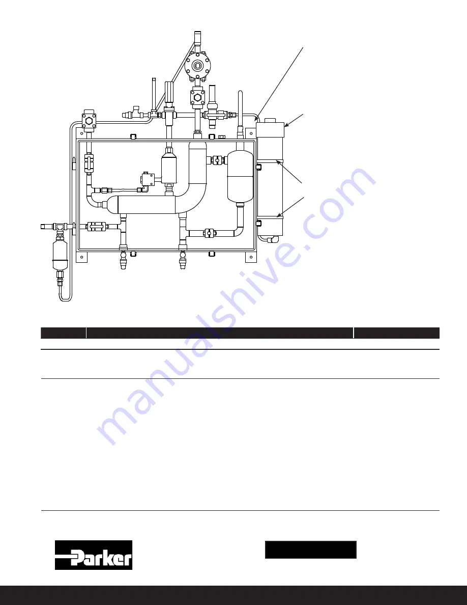
Cabinet Mounted Auto Purger - Bubbler Replacement Instructions
Step
Kit Description
Kit Number
3 - 4
Conversion Kit, Bubbler SS Tube to Nylon CS
208670
Cabinet Mounted Auto Purger Parts Kit