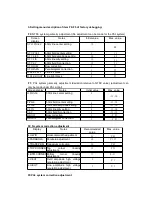
VII. Main IC Introduction
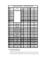
Serial
no.
Position
no.
Model
Function
1
N103
8899CPBNGXXX
CPU
2
N102
ATME24C08
Memory
3
N801
HM14053N
Logic conversion integrated block
4
N451
STV8172
Field scanning integrated block
5
N701
AN17821A
Sound power amplifier
6
N502
STR-W6556A
Power integrated block
7
TU201
ET-5C511-M04
Tuner
VIII. Notes for Factory Debugging
1.
Enter/exit factory mode
A. 1) Use factory remote control to enter factory mode
Use factory remote control:
Press FA key (Factory key) once to enter the factory debugging menu directly.
2) Use user remote control to enter factory mode
In TV state, press the “Menu” key, the main menu appears, then press the number keys
“2”, “4”, “8” and “3”.
Note: stop 2 to 3 seconds between “4” and “8”.
B. Method to return to the factory mode
A. User remote control:
1) Press DISP to directly return to the factory debugging menu.
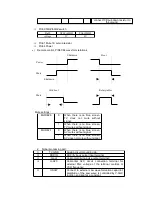
2) Press the power key to return to the factory state. When start again, the device
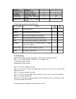
Pin
Symbol
Pin name
Function
1
D
Drain terminal
Transistor drain electrode
2
—
—
—
3
S/GND
Source electrode /
grounding terminal
Transistor electrode / grounding
4
Vcc
Power input terminal
Control power input
5
SS/ADJ
Soft-Start
over-current
protection terminal
Over-current protection adjustment and
Soft-Start time adjustment
6
FB
Feedback terminal
Fixed voltage control signal input,
intermittent oscillating control.
7
BD
Bottom detection terminal
Bottom detection signal input and external
latch signal input.


