


ENGLISH
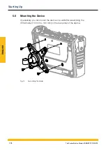
4.4.1 Inserting the Input Module
In order to be able to use the connection ports provided on the input
module, you must insert the input module in one of the slots in the de-
vice.
Input modules can be inserted or exchanged while the device is in op-
eration (hot plug or hot swap).
1
Loosen the two screws (1) in the dummy cover of the slot (e.g.
input module A) on the top of the device.
2
Remove the dummy cover from the slot and keep it in a safe
place.
3
Insert the input module (2) in the slot.
4
Tighten the two screws (1) hand-tight.
Ä
The input module is installed and ready to operate.
1
2
Fig. 7
Insert the input module
165
The Parker Service Master CONNECT V1.0/04/20
Input Modules
Содержание Service Master CONNECT
Страница 1: ...The Parker Service Master CONNECT Bedienungsanleitung Operating Manual ...
Страница 107: ...DEUTSCH Abb 55 Gerät Device 107 The Parker Service Master CONNECT V1 0 04 20 Bedienung ...
Страница 133: ...DEUTSCH 12 3 Maßzeichnungen 133 The Parker Service Master CONNECT V1 0 04 20 Anhang ...
Страница 134: ...DEUTSCH 134 The Parker Service Master CONNECT V1 0 04 20 Anhang ...
Страница 135: ...DEUTSCH 135 The Parker Service Master CONNECT V1 0 04 20 Anhang ...
Страница 137: ...DEUTSCH 137 The Parker Service Master CONNECT V1 0 04 20 Anhang ...
Страница 245: ...ENGLISH Fig 55 Device 245 The Parker Service Master CONNECT V1 0 04 20 Operation ...
Страница 271: ...ENGLISH 12 3 Dimensional Drawings 271 The Parker Service Master CONNECT V1 0 04 20 Appendix ...
Страница 272: ...ENGLISH 272 The Parker Service Master CONNECT V1 0 04 20 Appendix ...
Страница 273: ...ENGLISH 273 The Parker Service Master CONNECT V1 0 04 20 Appendix ...
Страница 275: ...ENGLISH 275 The Parker Service Master CONNECT V1 0 04 20 Appendix ...


