background image

 41

Parker Hannifin

Pump and Motor Division

Trollhättan, Sweden

Service Manual

Series V14

Bulletin HY30-5510-M1/UK

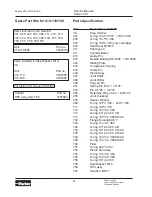
Item 

Torque (Nm) 

37 

105 ± 20

701 

1.2 ± 0.2 

704 

14 ± 4 

705 

26 ± 6 

706 

1.2 ± 0.2 

707 

1.2 ± 0.2

708 

38 ± 8 ISO

708 

25 ± 5 SAE 

716 

105 ± 20 

722 

13 ± 2 

733 

60 ± 10 

752 

40 ± 8

763 

38 ± 8 ISO

763 

25 ± 5 SAE

764 

40 ± 8

766 

3,4 ± 0,5

768 

31 ± 6

791 

22 ± 2

Splitview ADH Control

Содержание Series V14

Страница 1: ...Effective October 2014 Supersedes May 2012 Bulletin HY30 5510 M1 UK Service Manual Series V14...

Страница 2: ...ditions and applications for these products or systems the user through its own analysis and testing is solely responsible for making the final selection of the products and systems and assuring that...

Страница 3: ...r development of our well known V12 motor It is designed for both open and closed circuits intended particularly for mobile applications Important features carried over from previous motors Operating...

Страница 4: ...intermittent continuous Mass moment of inertia x10 3 kg m2 Weight kg 110 22 480 420 3900 3400 6500 5700 50 430 375 175 262 570 440 8 2 54 110 Max 6 seconds in any one minute 160 32 480 420 3400 3000 5...

Страница 5: ...12 0 40 48 5 19 0 26 3 85 20 0 48 0 12 3 41 48 0 20 0 26 6 86 19 0 48 5 12 7 42 47 5 20 5 27 0 87 18 5 49 5 13 0 43 46 5 21 0 27 3 88 17 5 50 0 13 3 44 46 0 21 5 27 7 89 17 0 51 0 13 6 45 45 5 22 0 28...

Страница 6: ...3 5 27 1 127 22 5 47 0 13 0 63 55 5 14 0 27 3 128 22 0 47 5 13 3 64 55 0 14 5 27 5 129 21 0 48 0 13 5 65 54 5 15 0 27 7 130 20 5 48 5 13 7 66 54 0 15 5 28 0 131 20 0 49 5 13 9 67 53 5 15 0 28 2 132 19...

Страница 7: ...12 13 14 15 8 Control modulating pressure current N AC AD 0 bar EP non selectable current A 15 bar1 AC AD AH HP B 25 bar1 AC AD AH HP C 50 bar1 AC AD AH D 80 bar1 AC AD AH 9 Valve options N None B Bra...

Страница 8: ...rmation on other shaft seals Size 1500 3000 4000 5000 6000 V14 110 max 10 1 6 1 5 5 2 4 5 Min and max case pressure bar vs shaft speed rpm V14 160 max 10 1 6 2 5 5 2 5 5 5 Required inlet pressure The...

Страница 9: ...em has reached full operating temperature the motor drain oil viscosity should be above 8 mm s cSt At start up the viscosity should not exceed 1500 mm s The ideal operating range for the V14 series is...

Страница 10: ...following controls satisfy most application requirements AC automatic pressure compensator AD Automatic pressure compensator with electric override and brake defeat AH automatic pressure compensator...

Страница 11: ...g chamber the setting spool moves to the right dis placement and output torque decreases At the same time the shaft speed increases correspondingly at a constant pump flow to the motor AC control func...

Страница 12: ...Note The distance between nut and screw end should not be more than 28 mm becau se of risk for loosing guiding of the spring 4 Increase the system pressure e g by blocking the motor shaft to desi red...

Страница 13: ...min and max displacements but no intermediate positions are available with these controls Module cross section EP shown 1 Two part seal 2 Control module housing 3 Treshold adjustment screw 4 Feedback...

Страница 14: ...re Refer to the illustration below right When the pilot pressure decreases the pilot piston retracts the servo valve spool moves to the right and flow is directed to the right hand setting chamber the...

Страница 15: ...ring is unloaded The distance between nut and screw end is approximately 22 mm when the threshold spring is unloaded Note If you remove solenoid or end cover the maximum distance between nut and screw...

Страница 16: ...ut One turn of the setting screw corre sponds to 48 bar When desired pressure level is reached tighten the locking nut 1 Install 0 600 bar 0 8500 psi gauges in port X1 and X4 and a 0 60 bar 0 850 psi...

Страница 17: ...spacers can be combi ned with each other s The thinnest spacer has to be mounted closest to the setting piston and the others in increasing length order Formula for determining the setting angle a at...

Страница 18: ...ries V14 Bulletin HY30 5510 M1 UK Remove the hexagon screws and lift the control module off Important Lift the control module straight up so the two check valve balls don t fall down into the motor Re...

Страница 19: ...Service Manual Series V14 Bulletin HY30 5510 M1 UK Remove the hexagon screws and lift the connection module Lift the valve segment Remove the cylinder barrel Note The support pin assembled between cy...

Страница 20: ...tor Division Trollh ttan Sweden Service Manual Series V14 Bulletin HY30 5510 M1 UK Remove the joint shaft Make sure all joint rollers follows Remove the support pin assembled bet ween joint shaft and...

Страница 21: ...anual Series V14 Bulletin HY30 5510 M1 UK Remove the compression spring Remove the pistons and the O ring fitted on the intermediate housing The pistons should be fitted in the same ball sockets as be...

Страница 22: ...tan Sweden Service Manual Series V14 Bulletin HY30 5510 M1 UK Remove the retaining ring Remove the seal carrier with shaft seal off Change the shaft seal Use the old shaft seal and press down the new...

Страница 23: ...Service Manual Series V14 Bulletin HY30 5510 M1 UK Remove the retaining ring Use a hydraulic press to remove the shaft Place something soft under the shaft to avoid damageing it Lift the bearing For...

Страница 24: ...in HY30 5510 M1 UK Assembling Install the bearing housing on the shaft Note Place the shaft on a distance Lubricate the shaft with oil Place the bearing on the shaft and press it down Note Be careful...

Страница 25: ...Pump and Motor Division Trollh ttan Sweden Service Manual Series V14 Bulletin HY30 5510 M1 UK Assemble the spacer washer and the re taining ring Assemble the O ring Lubricate the sealing surface with...

Страница 26: ...Hannifin Pump and Motor Division Trollh ttan Sweden Service Manual Series V14 Bulletin HY30 5510 M1 UK Assemble the seal ring carrier with shaft seal Assemble the retaining ring Assemble the compressi...

Страница 27: ...Trollh ttan Sweden Service Manual Series V14 Bulletin HY30 5510 M1 UK Assemble the guide pin Assemble the intermediate housing with O ring Assemble the pistons If the pistons isn t ex changed assembl...

Страница 28: ...UK Assemble the lower support pin Assemble the joint shaft Put some grease on the joint shaft so the rollers don t fall off Assemble the rollers with the chamfer in wards Assemble the upper support pi...

Страница 29: ...wards the cylinder barrel and the bronze side towards the valve segment Make sure that the support pin is in the correct position by using a thin pin and feel that it is in correct position The suppor...

Страница 30: ...ttan Sweden Service Manual Series V14 Bulletin HY30 5510 M1 UK Assemble the check valve balls Make sure that the guide pins are in place Assemble the control module fit the setting piston arm into the...

Страница 31: ...t screw counter clock wise Remove the spring kit Change the spring s Put the new spring kit in position and turn the adjustment screw clockwise until the spring is preloaded If you need to change the...

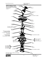
Страница 32: ...uded in sealkit 478 914476 470 11075 3786145 ISO 3786146 ISO speed 221 included in sealkit 440x9 3782326 433 3709175 455 3709887 454 3792387 483x2 118162 482 included in sealkit 447 3781043 415 includ...

Страница 33: ...are Parts V14 110 SAE Cartridge 3793183 3781043 3709887 3709889 3793192 3793185 118162 3706393 3709175 3788147 3788147 3782326 3709886 3792387 Shaft type S 3780458 S speed 3781155 S speed drain 378257...

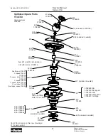
Страница 34: ...SO 60 10Nm SAE 110 22Nm 476 233 231 Splitview Spare Parts V14 160 3793440 3782233 3709754 3708046 3709756 3793185 3782630 3706669 3709175 3788146 3788146 3782400 3709761 914525 Shaft type S 3782372 S...

Страница 35: ...Series V14 Bulletin HY30 5510 M1 UK d ed Splitview A module 111 29 117x2 116x3 ISO 60 10 Nm SAE 110 22 Nm 420 822 828 13 3 Nm 823x2 825x2 50 10 Nm 116x3 835 824x2 890 875 818 133x2 105 20 Nm 20x2 816...

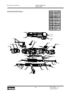
Страница 36: ...ide 712 716x6 733x8 731x2 710 707 721 722x4 708x2 741 747 742 747 701 743 748 712x2 706 745 744 749 757x2 772 783 36 781 37 720 45 703 37 36 705 704 732x2 711 790 791 780 782 746x4 722 Item Torque Nm...

Страница 37: ...2x4 708x2 721 722 708 747 741 742 747 753 748 749 752 750 746x4 744 743 745x2 713 712x2 757x2 701 751 706 732x2 711 790 791 782 780 772 783 781 37 36 705 704 703 45 720 36 37 722 Splitview AH Control...

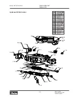
Страница 38: ...ntrol 706 722 710 740 733x8 731x2 732x2 716x6 711 706 701 712 712 723x3 723 722x5 701 A side B side 707 757x2 780 772 783 781 EP 782 790 791 712x2 37 36 705 704 703 45 720 36 37 Item Torque Nm 37 105...

Страница 39: ...746x4 741 748 722 706 701 712 712 A side B side 723 790 791 772 783 781 HP 780 701 711 706 732x2 707 710 782 720 45 712x2 703 37 36 757x2 705 37 36 704 716x6 723 722x5 Item Torque Nm 37 105 20 701 1...

Страница 40: ...783 772 769 screws and o rings are included in this item 732 757x2 712x2 732 731 731 733 733 722 706 701x2 716x6 711 708 710 722 746x4 748 741 723 702 707 Item Torque Nm 37 105 20 701 1 2 0 2 702 1 2...

Страница 41: ...nual Series V14 Bulletin HY30 5510 M1 UK Item Torque Nm 37 105 20 701 1 2 0 2 704 14 4 705 26 6 706 1 2 0 2 707 1 2 0 2 708 38 8 ISO 708 25 5 SAE 716 105 20 722 13 2 733 60 10 752 40 8 763 38 8 ISO 76...

Страница 42: ...ng 197 3 V80 224 3 V80 711 O ring 162 3 V70 712 O ring 12 3 2 4 V90 713 O ring 6 3 2 4 V80 AD 713 O ring 10 3 2 4 V80 AH AC 732 Flange Sealing SAE 1 743 O ring 11 3 2 4 V80 744 O ring 6 3 2 4 V80 AD 7...

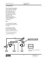
Страница 43: ...essure for externally supplied controls EP control requires an amplifier supplying correct current according to specification Test 1 Fill housing with hydraulic fluid and start the pump in the test st...

Страница 44: ...Parker Hannifin Pump and Motor Division Flygmotorv gen 2 SE 461 82 Trollh ttan Sweden Tel 46 0 520 40 45 00 Fax 46 0 520 371 05 www parker com...

Отзывы: