background image

708 Series 

High Pressure Titanium Positive Displacement Pump


24 


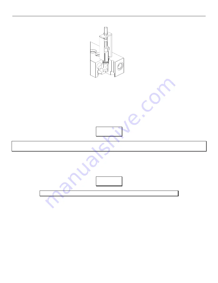
Fig. 10:  Weep Ring Extraction 


With a flat screwdriver remove the high-pressure seals (40). Manually remove the high-pressure seal spacer (40). 


You must clean and inspect the following parts for re-use: 

  Spacer, High-Pressure Seal (39): PN. 70-6016 

  Spacer, Low-Pressure Seal (39): PN. 70-6016 


Insert the high-pressure seal spacer (39) into the bore. 


Insert the high-pressure seal (40) into the bore until the seal is fully seated on the high-pressure seal spacer (39). 


Insert the weep ring (41) into the bore after the installation of the high-pressure seals (39). Install the snap ring (42) using 

the snap ring pliers. 


Insert the low-pressure seal spacer (39) and press in the new low-pressure seal (43).  The manifold seal servicing is 

complete. 

ATTACHING THE MANIFOLD TO THE CRANKCASE 


You will need these tools and parts to do the following: 

  9/16” Socket/ Socket Wrench (for 708-5) 

  1/2” Socket/ Socket Wrench (for 708-3) 

  3/16” Allen Wrench (for 708-1) 

  Dead Blow Hammer 

  Dead Blow Hammer 

  Manifold Bolt (58): PN. 70-6055 (for 708-5) 

  Manifold Bolt (58): PN. 70-6008 (for 708-3) 

  Manifold Screw (58): PN. 70-6046 (for 708-1) 

  Ceramic Lubricant: PN. 85-0087 

  Anti-Seize Lubricant: PN. 85-0094 


NOTE


A light coating of silicon grease (PN. 21-1122) should be used on all new o-rings and seals. 

Use of any other type of grease may result in o-ring or seal failure. 


NOTE


Ensure that the snap ring (42) is fully seated in the snap ring groove before continuing. 

Содержание Pure Water Series

Страница 1: ...Pure Water Series PW 400 2000 GPD Installation Operation Maintenance Village Marine PW 400 2000 Part Number 95 0025 ...

Страница 2: ......

Страница 3: ...THE PURE WATER SERIES 400 2000 GPD USER GUIDE REFERENCE MANUAL ...

Страница 4: ......

Страница 5: ...VERSE OSMOSIS THEORY 12 3 2 APPLICATION OF REVERSE OSMOSIS 12 3 3 PRODUCT WATER QUALITY STANDARDS 13 3 4 FACTORS AFFECTING PERMEATE PRODUCTION 14 3 4A TEMPERATURE CORRECTION FACTOR 15 3 5 OPERATIONAL DESCRIPTION 16 PRODUCT WATER MONITORING SYSTEM 16 MASTER CONTROL CENTER 16 REMOTE CONTROL CENTER OPTIONAL 16 PUSHBUTTON AND DISPLAY DESCRIPTIONS 17 3 6 CONTROLS AND INSTRUMENTATION 34 4 0 OPERATION 36...

Страница 6: ...W pH CLEANER 43 5 5 LONG TERM STORAGE PRESERVATION PROCEDURE 44 5 6 STEPS FOR PRESERVATION CHEMICAL 3 44 5 7 OIL CHANGE PROCEDURE 45 5 8 RO MOTOR LUBRICATION 46 6 0 MEMBRANE REPLACEMENT 48 6 1 PRESSURE VESSEL DISASSEMBLY 48 6 2 PRESSURE VESSEL ASSEMBLY 49 7 0 FREEZE PROTECTION 50 8 0 TROUBLESHOOTING 52 9 0 DRAWINGS AND DIAGRAMS 55 10 0 PARTS REFERENCE 79 11 0 MANUFACTURER S LITERATURE 109 ...

Страница 7: ......

Страница 8: ...SED FROM INSTALLATION DATE START UP PERFORMANCE READINGS MEASURE AFTER 3 AND 24 HOURS OR PRESSURIZED TIME IN SIMILAR CONDITIONS 3 Hours 24 Hours FEED WATER TEMPERATURE FEED WATER SALINITY IF KNOWN MAINS VOLTAGE FILTER PRESSURE AVERAGE AMP DRAW IF KNOWN OPERATING PRESSURE PRODUCT WATER FLOW GPH GPH REJECT WATER FLOW GPH GPH PRODUCT WATER QUALITY ppm ppm ...

Страница 9: ......

Страница 10: ...r million ppm HOW TO USE YOUR MANUAL This User Guide Reference Manual contains important information about the safe operation and maintenance of your Pure Water units We advise you to please read through the entire User Guide Reference Manual carefully to ensure you familiarize yourself with the operation of your RO system and follow the recommendations within the manual to help make your water pr...

Страница 11: ... inlet pressure 30 psi Flush water recommended maximum pressure 35 psi Design RO element pressure 800 psi Maximum RO element pressure 1000 psi Maximum feedwater chlorine residual 0 1 ppm Cleaning solution pH range 10 11 Chemical 1 2 3 Chemical 2 Membrane type Thin film composite Table 1 0 Performance Characteristics For inlet pressure greater than recommended limits install pressure regulator NOTE...

Страница 12: ...ua Pro High Pressure Pump Oil Kit Pump Service 85 0050 70 6184 85 0050 70 6184 Optional Big White filter housings use smaller filter elements 33 0052 and 33 0053 for 5 and 20 micron respectively Table 1 2 VMT Approved Consumables 1 5 MAINTENANCE EQUIPMENT Table 1 3 lists the test equipment for performance verification and maintenance of the RO unit Description VMT Part No Meter Hand Held 0 5000 pp...

Страница 13: ...he unit s maintenance i e membrane replacement oil change prefilter replacement or other services Figure 2 1 Recommended Installation Location BELOW waterline If the Pure Water FRAME cannot mount below the water line then the boost pump must be mounted separately below water line This can be very convenient with modular or semi modular formats where the boost pump is already separate see Figure 2 ...

Страница 14: ...four mounting holes through the frame and or mounting base When drilling ALWAYS CHECK for the drill bit from puncturing damaging any component of the watermaker and the surrounding mounting area 2 1b TO CONNECT PLUMBING Refer to SECTION 9 for the EXPANDED detailed Pure Water plumbing diagram for your model Follow the diagram to mount and connect all components Figure 2 3 Pure Water FRAME Plumbing ...

Страница 15: ...ter and Freshwater Flush Valve Figure 2 6 Carbon Filters with Freshwater Flush Valves Isometric Views NOTE Village Marine Tec recommends the Manual Freshwater Flush Assembly be installed BELOW waterline However the valve can be removed from the filter housing and relocated below waterline if it is difficult to get the filter housing that low A hose can be plumbed to the filter housing from the val...

Страница 16: ...ith Valve Connected Units with AUTOMATIC Freshwater Flush Assembly Mount the check valve component of the Automatic Freshwater Flush Valve Assembly BELOW waterline Refer to Figures 2 9 2 10 and 2 11 for views of the Carbon Filter and the Freshwater Flush Solenoid Valve Figure 2 9 Carbon Filters with Freshwater Flush Solenoid Valves Isometric Views ...

Страница 17: ... 2 10 or 2 11 for a diagram of the Automatic Freshwater Flush Assembly Figure 2 10 Typical Automatic Freshwater Flush Valve Assembly PW400 PW600 Diagram Figure 2 11 Automatic Freshwater Flush Valve Assembly Diagram for PW800 PW2000 ...

Страница 18: ...ot in the boat to install an overboard through hull Discharge line is required to be ABOVE waterline Refer to Figures 2 1 2 12 2 13 and 2 14 Figure 2 12 PURE WATER Brine Connection Overboard Figure 2 13 Pure Water SEMI MODULAR Brine Connection Overboard ...

Страница 19: ... the top of the product tank to prevent any possible back flow Village Marine Tec recommends teeing into the tank fill line Teeing into the tank vent line is possible if the vent is sufficient diameter to let air out of the tank while filling See Figures 2 15 2 16 and 2 17 Figure 2 15 PURE WATER Product Water Hose Connection ...

Страница 20: ... unit This will assure proper voltage even if power supply voltage is slightly less than required Never connect the RO unit to a line that services another electrical device THE RO UNIT SHOULD HAVE ITS OWN INDEPENDENT CIRCUIT BREAKER Verify all power switches and power sources are in the OFF position before any connection Carefully check the power supply volts phase and hertz on the PW serial numb...

Страница 21: ...l be reversed This condition called Reverse Osmosis can be established by artificially pressurizing the more concentrated solution using a high pressure pump In this type of system the concentrated solution normally referred to as feedwater will become more concentrated as pure water flows out of solution and across the membrane to the permeate side Discounting the effects of feedwater temperature...

Страница 22: ...of removing all 100 of the dissolved solids from seawater Designed to reject approximately 99 of the TDS the system allows 1 of the 32 000 ppm TDS in the seawater to pass into the product water This yields product water of less than 500 ppm the recommended TDS for drinking water A system such as this is said to have a salt passage of 1 Figure 3 1 Simplified Schematic of an RO System 3 3 PRODUCT WA...

Страница 23: ...ater or tap water applications Feed pressure shall not be increased above 950 psi The RO system can be adjusted to maintain a constant permeate output when feedwater temperature and salinity is other than nominal The operator can do this by controlling system pressure manually via the backpressure regulation valve located in the system brine piping As permeate flow decreases the operator can throt...

Страница 24: ...rection factor from Table 3 2 to give true system output under standard conditions 25 C Example Raw water temp 15 C TCF 1 47 Actual product flow 22 7 gph Calculation 22 7 x 1 47 33 369 gph Corrected product flow 33 gph Adjusted to 75 This is the normal flow for a PW 800 C Factor C Factor F Factor F Factor 1 3 64 26 0 97 34 3 47 84 0 88 2 3 23 26 0 94 36 3 18 86 0 82 3 3 03 28 0 91 38 3 18 88 0 79 ...

Страница 25: ... a signal is sent from the water quality monitor Figure 3 2 to the product diversion valve Figure 3 5 to reroute the high salinity water away from your water storage tank s and into the reject stream If the permeate TDS has LESS than 500 ppm indicating GOOD drinking water a signal is sent to the product diversion valve to redirect the good permeate through the product flowmeter and finally into yo...

Страница 26: ...ing through the product valve 5 DUMP CLEANING An illuminated yellow light activates when the product valve is de energized and the product valve is directing permeate to the reject line 6 SALINITY ALARM An illuminated red light indicates product water quality is above the WQM salinity set point MASTER CONTROL CENTER MCC AND REMOTE CONTROL CENTER RCC 7 LP PUMP Low Pressure Pump Controls the operati...

Страница 27: ... to determine actual cleaning frequencies MESSAGE CENTER DISPLAY ACTION STANDBY MODE LP PUMP ONLY HP PUMP ONLY RO MODE Unit is in preparation for use Low Pressure Boost Pump running only High Pressure pump running only NO LP PUMP running BOTH low and high pressure pumps OPERATING FLUSH Perform Freshwater Flush 0 2 Automatic timer countdown of Freshwater Flush CHECK PRODUCT WATER High salt content ...

Страница 28: ...sensor which provides a signal to the Master Control Center Depending on the concentration of total of dissolved solids TDS in the permeate the following occurs If the permeate TDS is detected AT GREATER than 500 parts per million ppm indicating POOR quality water a signal is sent from the Master Control Center Figure 3 2 to the three way product diversion valve Figure 3 3 to reroute the high sali...

Страница 29: ...erature value of the permeate line Has a range from 0 to 50 C 17 HOUR METER VALUE Displays the Hour Meter or Elapse Time Meter of the unit 18 TEMPERATURE Allows the operator to change the permeate temperature display between Fahrenheit F or Celsius C by touching the unit of measure 19 L PMP Low Pressure Pump Controls the operation ON OFF of the low pressure boost pump When the L PMP button changes...

Страница 30: ... SALINITY The screen will flash red Figure 3 4 when the permeate salinity goes above the salinity set point of 500 ppm In addition the product valve will de energize and divert the permeate away from the storage tank Figure 3 4 Red display screen when the permeate salinity is above the set point value of 500 ppm 2 LOW PRESSURE When a low pressure condition is present the low pressure warning will ...

Страница 31: ...g up the oil change notification window Figure 3 6 Figure 3 6 Oil change notification window Pressing the RESET button will reset this counter and remove the OIL icon while pressing the BACK button will return back to the display screen NOTE A display of 2000 ppm indicates the salinity of the water exceeds the detectable range for salinity The Master Control Center has a salinity detection range o...

Страница 32: ...ote Control Center MCC AND RCC DIFFERENCES Functions MCC RCC L PMP X X H PMP X X DUMP NORM X FLUSH X X MENU X X Set Permeate Salinity Offset X Set Permeate Temperature Offset X X High Salinity Audible Alarm Enabler X X Low Pressure Audible Alarm Enabler X X Silence Alarms X X Screensaver Enabler X X Screensaver Idle Time X X Set Permeate Salinity Set Point X X Set Flush Time X X Schedule Flush Ena...

Страница 33: ...efault in the system configuration screen Configuration Default Value Brightness 100 Salinity Offset 0 Temperature Offset 0 Salinity Set Point 500 Flush Time 2 Flush Schedule Enabler Disable Flush Schedule None Flush Schedule Time 8 00 Screensaver Enabler Enable Screensaver Time 1 Hibernate Enabler Enable Hibernate Time 5 Low Pressure Alarm Enabler Enable Salinity Alarm Enabler Enable Table 3 4 De...

Страница 34: ...e offset respectively Pressing the arrow UP and DOWN buttons will increment and decrement respectively The buttons C and F shows which unit of measure the offset is changing Pressing the BACK button will cancel any changes while pressing the ENTER button will save any changes See Section 5 9 for steps to calibrate the salinity and temperature values IMPROPER CALIBRATION WILL RESULT IN INACCURATE W...

Страница 35: ...e SILENCE ALARM will silence any audible alarms present 3 SCREENSAVER The screensaver configuration screen displays the screensaver enabler and the idle time before the screensaver activates Figure 3 12 Figure 3 12 Screensaver configuration screen Pressing the SCREENSAVER ENABLED DISABLED button will toggle between enabled BLACK and disabled GRAY for the screensaver Pressing the SET SCREENSAVER TI...

Страница 36: ...s while pressing the ENTER button will save any changes 4 SALINITY The salinity configuration screen displays the salinity set point value that will trigger a high salinity Figure 3 14 Figure 3 14 Salinity configuration screen Pressing the SET SALINITY SET POINT button will bring up the salinity set point entry screen Figure 3 15 Pressing the BACK button will return to the main menu screen ...

Страница 37: ...the ENTER button will save any changes 5 FLUSH The flush configuration screen displays length of time a flush will be enable Figure 3 16 Figure 3 16 Flush configuration screen Pressing the SET FLUSH TIME button will bring up the flush time entry screen Figure 3 17 Pressing the BACK button will return to the main menu screen SETTING THE SALINITY SET POINT ABOVE 500 IS NOT RECOMMENDED SET AT YOUR OW...

Страница 38: ...he enabler for the flush schedule and the start time of the auto flush Figure 3 18 Figure 3 18 Flush schedule configuration screen Pressing the SCHEDULE ENABLED DISABLED button will toggle between enabled BLACK and disabled GRAY for the auto flush Pressing the FLUSH SCHEDULE button will bring up the flush schedule entry screen Figure 3 19 Pressing the START TIME button will bring up the flush sche...

Страница 39: ...while pressing the ENTER button will save any changes Figure 3 20 Flush schedule start time entry screen Pressing the arrow UP and DOWN buttons will increment and decrement respectively Pressing the BACK button will cancel any changes while pressing the ENTER button will save any changes 7 HIBERNATE The hibernate configuration screen displays the hibernate enabler and the idle time before the hibe...

Страница 40: ...ng the BACK button will return to the main menu screen Figure 3 22 Hibernate idle time entry screen Pressing the arrow UP and DOWN buttons will increment and decrement respectively Pressing the BACK button will cancel any changes while pressing the ENTER button will save any changes 8 SYSTEM The system configuration screen displays the button to restore the default configurations in Table 3 4 the ...

Страница 41: ...n 1 Figure 3 23 will return to the main menu screen Pressing the NEXT button will navigate to the system configuration screen 2 Figure 3 24 Pressing the SET DATE button will bring up the set system date entry screen Figure 3 26 Pressing the SET TIME button will bring up the set system time entry screen Figure 3 27 Pressing the BACK button on the system configuration screen 2 Figure 3 24 will retur...

Страница 42: ...ate entry screen Figure 3 27 Set system time entry screen Pressing the arrow UP and DOWN buttons will increment and decrement respectively Pressing the BACK button will cancel any changes while pressing the ENTER button will save any changes ...

Страница 43: ...ater not converted into fresh discharged from the RO unit FM2 Product Water Flow Meter Indicates the rate of fresh water production by the RO unit HP PUMP HP Pump Start Stop Button Provides operational control of the HP Pump LP PUMP LP Boost Pump Start Stop Button Provides operational control of the Low Pressure LP Boost Pump MON Water Quality Monitor See Section 3 5 for detailed description MC2 H...

Страница 44: ... Valve Maintains and controls system back pressure V4 Product Diversion Valve Based on its salinity directs permeate to either the potable water tank s or to drain V5 Filter Bleed Check Valve Prevents reject flow from back flowing through the filter housings into the feed water stream V6 3 Product Water Relief Valve Relieves product water pressure when Product Diversion Valve is shut Factory set a...

Страница 45: ...ster controller should now display STANDBY Step 4 Start the Low Pressure Boost Pump by pressing the LP PUMP pushbutton located on the Master Control Center or on the Remote Control Center Refer to Figures 3 2 and 3 4 Verify the Vacuum Gauge shows positive pressure normally 10 to 15 psi Step 5 Start the High Pressure Pump by pressing the HP PUMP pushbutton located on the Master Control Center panel...

Страница 46: ...olution water must be diverted AT LEAST 10 MINUTES to clear preservative solution from system Step 10 Check the RO unit for water leakage periodically at the initial start up Observe Product Flow meter Record the operating data after 3 and 24 hours of operation use the startup sheet provided on page V NOTE For Remote Control Operation The initial start up procedure must be followed FIRST prior to ...

Страница 47: ...LEANING POSITION This procedure allows release of the high pressure air trapped within the system Verify the Cleaning Valve Gray Valve is positioned to NORMAL discharge FAILURE TO OPEN THE HIGH PRESSURE BYPASS VALVE WHICH IS REQUIRED TO RELEASE ANY TRAPPED AIR COULD RESULT IN HYDRAULIC SHOCK TO THE SYSTEM Step 3 Verify the seawater intake is open at the through hull This allows the feed seawater t...

Страница 48: ...unit VOIDING factory warranty and may also risk personal injury NOTE At initial start up of RO unit PRESS DUMP on the Master Control to keep the product water diverted from the water storage tank IF the unit is filled with preservative storage solution water must be kept running AT LEAST 30 MINUTES to clear preservative solution from system Step 11 Check the RO unit for water leakage periodically ...

Страница 49: ...ds is in contact with the membranes A freshwater flush procedure is necessary to prevent clogging and growth of organic contaminants in the RO system and its membranes The flush pushes out older stagnant seawater saltwater out of the membranes and replacing it with freshwater non saltwater leaving less chance of fouling the membranes The freshwater flush procedure should be used when the unit will...

Страница 50: ...ater supply branch Step 3 Press the FLUSH pushbutton located on the Master Control Center on the electronic instrument panel or the Remote Control Center if equipped This will automatically begin the freshwater flush cycle within the RO system The electronic flush will automatically start the Low Pressure Boost Pump then the High Pressure Pump and begin the flushing process for a period of two min...

Страница 51: ... GREASE BIOLOGICAL MATTER AND GRIME FROM THE SURFACE OF THE RO MEMBRANES SEE WARNING LABEL ON SIDE OF PACKAGE AND OBSERVE ALL SAFETY PRECAUTIONS ON LABEL CLEANING CHEMICAL 2 IS AN ACID A MINERAL SCALE REMOVER SEE WARNING LABEL ON SIDE OF PACKAGE AND OBSERVE ALL SAFETY PRECAUTIONS ON LABEL THE USE OF CHEMICALS OR CLEANING METHODS OTHER THAN THOSE OUTLINED IN THIS MANUAL WILL VOID THE RO UNIT WARRAN...

Страница 52: ...and 3 4 Verify the Vacuum Pressure Gauge reads more than zero 0 psi Temporarily opening the flush valve can assist in building cleaning loop pressure Step 8 After the chemical solution circulated through the RO for 3 minutes shutdown the HP PUMP and LP PUMP respectively a Remove the lid to the filter tank and manually sample the filter water Measure the pH level of the sample using test kit 90 013...

Страница 53: ...TY PRECAUTIONS ON LABEL Step 3 Verify that the black High Pressure Bypass Valve is in the CLEANING open position Step 4 Place the gray cleaning valve in the CLEANING position Step 5 Remove one of the prefilter housing lids and pour in the preservative solution prepared in Step 3 Step 6 Start the Low Pressure Boost Pump by pressing the LP PUMP pushbutton located on the Master Control Center or on t...

Страница 54: ... oil replacement process by running the RO unit to heat the oil Heating the oil reduces the viscosity allowing it to be more fluid to travel through the drain tube THE PURE WATER UNIT OIL CHANGE PROCEDURE Figure 5 1 PURE WATER HP Pump and Motor Step 1 Before changing the oil obtain a container i e a small tray or catch basin to collect the oil drainage Step 2 Remove the oil plug Refer to Figure 5 ...

Страница 55: ...ely bearing malfunction Introduce grease into motor slowly Location Type High Pressure Pump Village Marine Tec Pump Oil P N 85 0050 High Pressure Pump Motor Chevron SRI Grease NGLI 2 ExxonMobil PolyrexEM Grease Shell Oil Dolium R NGLI 2 Texaco Premium RB O rings and Gaskets Glycerin or Silicone Lubricant Table 5 3 Motor and HP Pump Lubrication Requirements DO NOT mix grease types Keep consistent t...

Страница 56: ...MAINTENANCE Table 5 4 Sample Operational Log Date Total Hours HP Pump Inlet Pressure RO Array Pressure Product Flow GPH Brine Flow GPH Prod water TDS ppm Water Temp C ...

Страница 57: ... pressure vessel end collar Place an appropriate sized slot screwdriver in each slot Twist both screwdrivers until the end plug breaks loose from the pressure vessel The screwdrivers can now be placed between the end plug and collar A prying motion on both sides of the end plug with the screwdrivers will quickly remove it Use this procedure for both end caps Step 4 Push or pull the membrane elemen...

Страница 58: ...irst Slide membrane into pressure vessel until resistance is felt Continue applying pressure until the product water tube sits into the end plug Step 3 Install the remaining end plug align end plug holes with mounting studs properly use the reference mark made in step 3 for correct assembly Step 4 Tighten the six fasteners for each end cap Step 5 Reconnect plumbing to pressure vessel s NOTE Do not...

Страница 59: ...ater Flush Valve is positioned for seawater intake NOT freshwater Step 4 Start the Low Pressure Boost Pump by pressing the LP PUMP pushbutton located on the Master Control Center or on the Remote Control Center Refer to Figures 3 2 and 3 4 Step 5 Start the High Pressure Pump by pressing the HP PUMP pushbutton located on the Master Control Center panel or on the Remote Control Center Refer to Figur...

Страница 60: ...instructions in SECTION 5 4 STEPS FOR PRESERVATION CHEMICAL 3 Step 2 Remove membrane vessels from the boat placing caps over the fittings This is a more practical alternative for Pure Water MODULAR systems Membranes must be kept wet with preservative solution so snug caps are required Step 2 Store the membranes in an environment protected from freezing Step 3 Drain the entire RO of all remaining w...

Страница 61: ...gh the brine discharge Flow should be about 3 to 5 GPM 2 Always check for loose connections or broken wires when checking electrical parts Check for good voltage at the high pressure pump motor and if it is low then follow back with the voltmeter until the loose connection is found 3 Confirm that a free sea water feed is supplied A The through hull is clear of trash or kelp B Seacock is open C Sea...

Страница 62: ...TROUBLESHOOTING Figure 8 0 Troubleshooting Flow Diagram T ...

Страница 63: ...TROUBLESHOOTING Figure 8 0 Troubleshooting Flow Diagram CONTINUED T ...

Страница 64: ...DRAWINGS AND DIAGRAMS 38 VMT v JUNE 2008 9 0 DRAWINGS AND DIAGRAMS ...

Страница 65: ......

Страница 66: ......

Страница 67: ......

Страница 68: ...Pure Water Semi Modular 600 PWSM 600 Plumbing Diagram Village Marine Tec Freshwater From the Sea November 2004 ...

Страница 69: ...Pure Water Semi Modular 800 1200 PWSM 800 1200 Plumbing Diagram Village Marine Tec Freshwater From the Sea November 2004 ...

Страница 70: ...Pure Water Semi Modular 1600 2000 PWSM 1600 2000 Plumbing Diagram Village Marine Tec Freshwater From the Sea 2008 ...

Страница 71: ...Pure Water Modular 400 PWM 400 Plumbing Diagram Village Marine Tec Freshwater From the Sea November 2004 ...

Страница 72: ...Pure Water Modular 600 PWM 600 Plumbing Diagram Village Marine Tec Freshwater From the Sea November 2004 ...

Страница 73: ...Pure Water Modular 800 1200 PWM 800 1200 Plumbing Diagram Village Marine Tec November 2004 Freshwater From the Sea ...

Страница 74: ...Pure Water Modular 1600 2000 PWM 1600 2000 Plumbing Diagram Village Marine Tec 2008 Freshwater From the Sea ...

Страница 75: ......

Страница 76: ......

Страница 77: ......

Страница 78: ......

Страница 79: ......

Страница 80: ......

Страница 81: ......

Страница 82: ......

Страница 83: ......

Страница 84: ......

Страница 85: ......

Страница 86: ......

Страница 87: ......

Страница 88: ......

Страница 89: ......

Страница 90: ......

Страница 91: ...PARTS REFERENCE 62 VMT v JUNE 2008 Drawing upgrade as of 4 1 2015 ...

Страница 92: ......

Страница 93: ......

Страница 94: ......

Страница 95: ......

Страница 96: ......

Страница 97: ......

Страница 98: ......

Страница 99: ......

Страница 100: ......

Страница 101: ......

Страница 102: ......

Страница 103: ......

Страница 104: ...PARTS REFERENCE 39 VMT v JUNE 2008 10 0 PARTS REFERENCE ...

Страница 105: ......

Страница 106: ......

Страница 107: ......

Страница 108: ......

Страница 109: ......

Страница 110: ......

Страница 111: ......

Страница 112: ......

Страница 113: ......

Страница 114: ......

Страница 115: ......

Страница 116: ......

Страница 117: ......

Страница 118: ......

Страница 119: ......

Страница 120: ......

Страница 121: ......

Страница 122: ......

Страница 123: ......

Страница 124: ...MANUFACTURER S LITERATURE 92 VMT v JUNE 2008 Drawing upgrade as of 4 1 2015 ...

Страница 125: ...ERWISE NOTED ALL DIMENSIONS ARE IN INCHES IN AND MILLIMETER mm TITLE PROJECT CUSTOMER DWG NO PREPARED BY CHECKED BY APPROVED BY DATE DATE DATE REV WEIGHT SHT OF AZ 3 25 2015 PK 3 25 2015 KS 3 25 2015 90 8633 1 E Engineering SRC Leisure Marine Product Development 2 STANDARD UNITS VMT COMPACT UNITS PW 400 2000 90 8633 PW 400 110 1 60 400GPD DESALINATOR iam DRAWING STATUS PRODUCTION RELEASE CUSTOMER ...

Страница 126: ...8 8 A A B B C C D D Parker Water Purification 2630 El Presidio St Carson California 90810 USA Tel 310 637 3400 Fax 310 999 6262 www parker com PROPRIETARY NOTICE This drawing includes confidential information of Parker Hannifin Corporation which is provided for the sole purpose of permitting the recipient to evaluate the design or proposal submitted herewith In consideration of receipt of this doc...

Страница 127: ...AND MILLIMETER mm TITLE PROJECT CUSTOMER DWG NO PREPARED BY CHECKED BY APPROVED BY DATE DATE DATE REV WEIGHT SHT OF AZ 7 22 2014 PK 9 23 2014 RI 9 23 2014 90 8637 1 E Engineering SRC Leisure Marine Product Development 2 STANDARD UNITS VMT COMPACT UNITS PW 400 2000 90 8637 PW 800 220 3 60 FRAME DESALINATOR iam DRAWING STATUS PRODUCTION RELEASE CUSTOMER P O 422 557 lbmass SCALE NTS FRACTIONS X XX XX...

Страница 128: ...10 637 3400 Fax 310 999 6262 www parker com PROPRIETARY NOTICE This drawing includes confidential information of Parker Hannifin Corporation which is provided for the sole purpose of permitting the recipient to evaluate the design or proposal submitted herewith In consideration of receipt of this document the recipient agrees to maintain such information in confidence and not reproduce or otherwis...

Страница 129: ...LIMETER mm TITLE PROJECT CUSTOMER DWG NO PREPARED BY CHECKED BY APPROVED BY DATE DATE DATE REV WEIGHT SHT OF AZ 7 22 2014 PK 9 23 2014 RI 9 23 2014 90 8606 1 E Engineering SRC Leisure Marine Product Development 2 STANDARD UNITS VMT COMPACT UNITS PW 400 2000 90 8606 PW 1200 230 1 50 FRAME DESAL INATOR iam DRAWING STATUS PRODUCTION RELEASE CUSTOMER P O 406 114 lbmass SCALE NTS FRACTIONS X XX XXX ANG...

Страница 130: ...l 310 637 3400 Fax 310 999 6262 www parker com PROPRIETARY NOTICE This drawing includes confidential information of Parker Hannifin Corporation which is provided for the sole purpose of permitting the recipient to evaluate the design or proposal submitted herewith In consideration of receipt of this document the recipient agrees to maintain such information in confidence and not reproduce or other...

Страница 131: ...S IN AND MILLIMETER mm TITLE PROJECT CUSTOMER DWG NO PREPARED BY CHECKED BY APPROVED BY DATE DATE DATE REV WEIGHT SHT OF AZ 7 22 2014 PK 9 23 2014 RI 9 23 2014 90 8603 1 E Engineering SRC Leisure Marine Product Development 2 STANDARD UNITS VMT COMPACT UNITS PW 400 2000 90 8603 PW 1600 220 3 60 FRAME DESALINATOR iam DRAWING STATUS PRODUCTION RELEASE CUSTOMER P O 539 313 lbmass SCALE NTS FRACTIONS X...

Страница 132: ... 310 999 6262 www parker com PROPRIETARY NOTICE This drawing includes confidential information of Parker Hannifin Corporation which is provided for the sole purpose of permitting the recipient to evaluate the design or proposal submitted herewith In consideration of receipt of this document the recipient agrees to maintain such information in confidence and not reproduce or otherwise disclose the ...

Страница 133: ...D MILLIMETER mm TITLE PROJECT CUSTOMER DWG NO PREPARED BY CHECKED BY APPROVED BY DATE DATE DATE REV WEIGHT SHT OF AZ 7 22 2014 PK 9 23 2014 RI 9 23 2014 90 8598 1 E Engineering SRC Leisure Marine Product Development 2 STANDARD UNITS VMT COMPACT UNITS PW 400 2000 90 8598 PW 2000 380 3 50 FRAME DESALINATOR iam DRAWING STATUS PRODUCTION RELEASE CUSTOMER P O 456 332 lbmass SCALE NTS FRACTIONS X XX XXX...

Страница 134: ... PROPRIETARY NOTICE This drawing includes confidential information of Parker Hannifin Corporation which is provided for the sole purpose of permitting the recipient to evaluate the design or proposal submitted herewith In consideration of receipt of this document the recipient agrees to maintain such information in confidence and not reproduce or otherwise disclose the information to any person ou...

Страница 135: ...MANUFACTURER S LITERATURE 40 VMT v JUNE 2008 11 0 MANUFACTURER S LITERATURE ...

Страница 136: ......

Страница 137: ...IST 12 DETACHING THE MANIFOLD FROM THE CRANKCASE 13 ROUTINE SERVICE KIT 13 VALVE ASSEMBLY ROUTINE SERVICE 13 MANIFOLD SEAL ROUTINE SERVICE 14 CRANKCASE SEAL ROUTINE SERVICE 15 SERVICING THE CRANKCASE 15 OIL DRAIN PLUG O RING REPLACEMENT 17 PLUNGER ROD SEAL REPLACEMENT 17 BEARING SIDE PLATE O RING SEAL REPLACEMENT 18 CRANKCASE COVER O RING REPLACEMENT 19 CRANKSHAFT BEARING CONNECTING ROD PISTON ASS...

Страница 138: ...14 Fig 4 Orientation for Manifold Seal Servicing 15 Fig 5 Plunger Retaining Bolt Assembly 16 Fig 6 Seal Retainer 16 Fig 5 Plunger Retaining Bolt Assembly 18 Fig 6 Seal Retainer 18 Fig 7 Manifold Assembly 21 Fig 8 Valve Assembly 22 Fig 9 Orientation for Manifold Seal Servicing 23 Fig 10 Weep Ring Extraction 24 ...

Страница 139: ...LIST OF TABLES Table 1 Approximate Horsepower Required 3 Table 2 Tool List For Pump Service 12 ...

Страница 140: ...re Flooded to 60 PSI Maximum Fluid Temperature 120 degrees Fahrenheit 82 degrees Celsius Model Number Capacity Inlet Port Size Discharge Port Size Dimensions L x W x H Weight Shaft 708 1 15 GPH 50 NPT 25 NPT 9 125 x 5 5 x 4 11 lbs 625 708 1 22 GPH 50 NPT 25 NPT 9 125 x 5 5 x 4 11 lbs 625 708 1 29 GPH 50 NPT 25 NPT 9 125 x 5 5 x 4 11 lbs 625 708 3 2 3 GPM 75 NPT 5 MS16142 8 7 5 x 6 x 4 5 18 9 lbs 6...

Страница 141: ...SIGN To drive the pump to give the desired discharge volume for your specific application equation 2 1 is to be used PULLEY SELECTION It is essential that an appropriate pulley size be selected to meet your application needs Based on the required pump discharge volume in GPM the correct pulley size can be selected using equation 2 2 WARNING This is a positive displacement pump A properly designed ...

Страница 142: ... Pressure PSI Flow GPH Speed RPM 800 1000 29 710 26 33 28 686 26 32 27 661 25 31 16 637 24 30 HP Required 708 3 2 3 GPM Working Pressure PSI Flow GPM Speed RPM 800 1000 2 5 1774 1 37 1 71 2 3 1632 1 26 1 58 2 0 1419 1 10 1 37 1 5 1064 82 1 03 HP Required 708 3 3 5 GPM Working Pressure PSI Flow GPM Speed RPM 800 1000 4 1530 2 19 2 74 3 5 1339 1 92 2 40 3 1148 1 64 2 05 2 765 1 10 1 37 HP Required 7...

Страница 143: ...ve must be installed to prevent over pressure in the event that the discharge or down stream plumbing becomes restricted or is turned off Severe damage to the pump will result if this condition occurs without a relief valve in the line On fittings not using o ring seals use PTFE liquid sparingly or tape to connect accessories or plumbing Do not wrap tape beyond the last thread to prevent tape from...

Страница 144: ... this requirement Provide adequate baffling in the tank to eliminate air bubbles and turbulence Install diffusers on all return lines to the tank INLET LINE SIZE Inlet line size should be adequate to avoid starving the pump Pump suction should never operate in a vacuum 1 Line size must be sufficient to allow free flow of influent fluid at the pumping flow rate Minimize the use of thick walled fitt...

Страница 145: ...t over pressurization control inlet flow contamination or temperature and provide ease of servicing 1 An inlet supply shut off valve is recommended to facilitate maintenance 2 A standpipe can be used in some applications to help maintain a positive head in the inlet line 3 Inspect and clean the inlet filters on a regular schedule if applicable 4 A vacuum pressure gauge should be installed to monit...

Страница 146: ...pendability and performance Not performing these tasks could result in catastrophic failure TASKS DAILY WEEKLY FIRST 100 HRS EVERY 500 HRS EVERY 1500 HRS PLAN FOR EVERY 3000 HRS EVERY 10000 HRS INSPECTION TASKS Clean Filters X Water Leaks X Oil Level X Pulley X Belts X Inspect Plumbing X SERVICE TASKS Pump Oil X X Routine Service Kit X Crankcase Rebuild Kit X Manifold Rebuild Kit X Crankshaft Bear...

Страница 147: ...NATURE DATE 100 Oil 500 Oil 1000 Oil 1500 Service Kit Oil 2000 Oil 2500 Oil 3000 Service Kit Full Kit Oil 3500 Oil 4000 Oil 4500 Service Kit Oil 5000 Oil 5500 Oil 6000 Service Kit Full Kit Oil 6500 Oil 7000 Oil 7500 Service Kit Oil 10000 Crankshaft Bearing Oil Replace HP seal only in case of failure see low pressure troubleshooting pg 9 Hours are for reference only for maintenance planning purpose...

Страница 148: ...eplace with a rebuild kit Worn high pressure seals abrasives in pump fluid severe cavitation inadequate water supply stressful inlet conditions Replace seals with manifold rebuild kit not service kit Install and maintain proper filter check line size and flow available to pump Pulsation pump runs extremely rough pressure low Faulty pulsation dampener if a pulsation dampener has been installed Chec...

Страница 149: ...kit not service kit Excessive play in the end of the crankshaft Worn bearing Replace bearing Oil leaking in the rear portion of the crankcase Damaged or improperly installed crankcase cover crankcase cover o ring drain plug or drain plug o ring Replace crankcase cover o ring or drain plug o ring Loud knocking noise in pump Pulley loose on crankshaft Check key and tighten setscrew Restricted Inlet ...

Страница 150: ...harge valve or worn inlet or discharge valves Check for smooth surfaces on inlet and discharge valve seats If signs of wear or damage are present return to factory for service Check supply tank for contamination regularly clean filter Do not pump abrasive fluid Restricted fluid flow Check the Inlet Conditions Checklist ...

Страница 151: ...e any part of the pump TOOLS NEEDED Table 2 Tool List for Pump Service 3 16 Allen Wrench Phillips Head Screwdriver 1 4 Allen Wrench Pick 7 16 Socket Socket Wrench or Combination Wrench Snap Ring Pliers 9 16 Socket Socket Wrench or Combination Wrench Torque Wrench 220 in lb 1 2 Socket Socket Wrench or Combination Wrench Weep Ring Removal Tool PN 91 3827 3 4 Socket Socket Wrench or Combination Wrenc...

Страница 152: ...ea If the manifold assembly locating dowel pins 53 fall out reinsert them into the manifold alignment pin holes Fig 2 Manifold Assembly Removal ROUTINE SERVICE KIT The following are the part numbers for the 708 Series Routine Service Kits 708 1 Routine Service Kit PN 70 6181 708 3 2 3 Routine Service Kit PN 70 6182 708 3 3 5 Routine Service Kit PN 70 6183 708 5 Routine Service Kit PN 70 6184 The M...

Страница 153: ... Complete valve assembly shown in Fig 3 Fig 3 Valve Assembly NOTE There are two different valve plug designs Inspect the manifold 38 for debris or other fouling and clean if necessary Inspect the valve seat surface in the manifold If there is a problem contact your dealer Reinstall all the valve plug assemblies with a 7 8 socket wrench or combination wrench and tighten MANIFOLD SEAL ROUTINE SERVIC...

Страница 154: ... the pick remove the plunger rod oil seal 7 from the crankcase Inspect the seal retainer washers 8 for damage if none evident then reuse if damage is evident consult the factory Insert new plunger rod oil seal 7 into crankcase making sure that the seal is fully seated place outer washer 6 on seal Place slinger 25 onto the plunger rod 9 Slide ceramic plungers 26 onto plunger rod and insert the plun...

Страница 155: ...socket Apply Aqua Pro s special Ceramic Lubricant PN 90 1604 to the ceramic plungers 26 Slide the seal retainer over the ceramic plungers 26 Make sure that the flanged side is close proximity to the manifold assembly and that hole is oriented downward ensuring that the seal retainer has adequate water drainage Fig 6 Seal Retainer Routine service is now complete NOTE Be CAREFUL not to get the red l...

Страница 156: ...ls and parts to do the following 7 16 Socket Socket Wrench Torque Wrench Seal Oil Plunger Rod 7 PN 70 6018 Washer Plunger Retainer 27 PN 70 6035 O Ring Plunger Retainer 26 PN 70 6012 Slinger Barrier 24 PN 70 6015 Ceramic Lubricant PN 85 0087 Silicone Grease Lubricant PN 21 1122 Red Loctite 262 Lint free Cloths Remove the seal retainer 29 and set aside Remove the plunger retainer bolt 28 with a 7 1...

Страница 157: ...er retainer bolt 29 and torque to 100 in lb using a 7 16 socket Apply Aqua Pro s special Ceramic Lubricant PN 90 1604 to the ceramic plungers 26 Slide the seal retainer over the ceramic plungers 26 Make sure that the flanged side is close proximity to the manifold assembly and that hole is oriented downward ensuring that the seal retainer has adequate water drainage Fig 6 Seal Retainer BEARING SID...

Страница 158: ... side bearing cap 17 Install o ring 15 in o ring groove on the crankshaft bearing caps 16 17 and reinstall caps on pump Install the 4 socket head cap screws 19 onto each of the bearing side plates and tighten with a 1 4 Allen Wrench This applies to the 708 1 708 3 3 5 GPM and the 708 5 pumps For the 708 3 2 3 GPM pump reinstall the bell housing 34 by installing the 4 Philips head screws 36 CRANKCA...

Страница 159: ...intenance other than rebuild and service kits voids the warranty if not performed by factory trained personnel SERVICING THE MANIFOLD The following are the procedures for servicing the crankcase assembly using the 708 1 Manifold Rebuild Kit PN 70 6079 708 3 2 3 GPM Manifold Rebuild Kit PN 70 6110 708 3 3 5 GPM Manifold Rebuild Kit PN 70 6111 708 5 Manifold Rebuild Kit PN 70 6105 8 GPM Pump Manufac...

Страница 160: ...o rings 48 from each of the adapters Install the new o rings 48 provided with the kit onto each of the adapters Reinstall each of the adapters onto the manifold assembly tighten adapter with 3 4 Socket Socket Wrench VALVE ASSEMBLY SERVICING You will need these tools and parts to do the following 7 8 Socket Wrench or Combination Wrench Pick NOTE A light coating of silicon grease PN 21 1122 should b...

Страница 161: ...e plug o ring 46 onto valve plug 47 Install the valve spring 45 onto the valve plug 47 it should now be attached to the plug Press the valve 44 onto the valve spring 45 Complete valve assembly shown in Fig 9 Fig 8 Valve Assembly NOTE There are two different valve plug designs Inspect the manifold 38 for debris or other fouling and clean if necessary Inspect the valve seat surface in the manifold I...

Страница 162: ...the seals for removal and installation as shown in Fig 10 Fig 9 Orientation for Manifold Seal Servicing With a flat screw driver remove the low pressure seal 43 Manually remove the low pressure seal spacer 39 With the snap ring pliers remove the snap ring 42 Using the weep ring extracting tool remove the weep ring assembly 41 as shown in Fig 11 NOTE Pump manifold assembly must be detached from the...

Страница 163: ...ing 42 using the snap ring pliers Insert the low pressure seal spacer 39 and press in the new low pressure seal 43 The manifold seal servicing is complete ATTACHING THE MANIFOLD TO THE CRANKCASE You will need these tools and parts to do the following 9 16 Socket Socket Wrench for 708 5 1 2 Socket Socket Wrench for 708 3 3 16 Allen Wrench for 708 1 Dead Blow Hammer Dead Blow Hammer Manifold Bolt 58...

Страница 164: ... seal retainers are installed with the flange located away from the crankcase assembly Align manifold assembly to crankcase assembly and tighten the two manifold bolts 58 with a 9 16 socket wrench for the 708 5 with a 1 2 socket wrench for the 708 3 or the 4 socket head bolts with the 3 16 Allen wrench for the 708 1 NOTE A light coating of Anti Seize Lubricant PN 85 0094 should be applied on all t...

Страница 165: ...708 Series High Pressure Titanium Positive Displacement Pump 26 ...

Страница 166: ...708 5 DRAWINGS ...

Страница 167: ...G CAP 2 2 14 70 6060 BEARING GUIDE 708 5 1 13 70 1281 RING SNAP BEARING 708 SERIES 1 12 70 6059 CRANKSHAFT 708 5 8 GPM 1 11 70 6033 ASSY CONNECTING ROD 708 SERIES 5 10 70 0382 PIN DOWEL DRIVE ASSY 5 9 70 6067 PLUNGER 708 SERIES 5 8 70 6019 WASHER OIL SEAL INNER 708 SERIES 5 7 70 6018 SEAL OIL 708 SERIES 5 5 5 6 70 6017 WASHER OIL SEAL OUTER 708 SERIES 5 5 70 0696 PLUG OIL DRAIN 1 4 30 1286 O RING ...

Страница 168: ... QTY REBUILD KIT QTY SERVICE KIT 55 NOT USED 54 NOT USED 53 70 6087 PIN MANIFOLD 708 SERIES 2 52 30 0441 ADAPTER LP INLET 708 3 5 1 51 30 0573 PLUG LP INLET 708 3 5 1 50 70 3052 PLUG HP DISCHARGE 708 3 5 1 49 30 1082 ADAPTER HP DISCHARGE 708 SERIES 1 48 30 1286 O RING PLUG OIL DRAIN HP DISCHARGE 2 2 47 70 0660 PLUG VALVE HD 708 SERIES 10 46 70 6002 O RING OIL DRAIN VALVE PLUG 10 10 10 45 70 6003 S...

Страница 169: ...E AS FOLLOWS NOTES ITEM NO PART NUMBER DESCRIPTION QTY 58 70 6055 BOLT 50 13UNC 2A SHOULDER 2 57 70 6123 ASSEMBLY 708 5 MANIFOLD 1 56 70 6127 ASSY CRANKCASE 708 5 1 REV D C B A A B C D 1 2 6 7 8 8 7 6 5 4 3 2 1 SIZE B TITLE SHEET 1 OF 1 J RODRIGUEZ 4 DATE 03 14 05 ASSEMBLY 708 5 MAIN 5 3 56 58 57 ...

Страница 170: ...la tor comes with a full one year guarantee backed by years of Village Marine Tec experience and technology These pressure regulators come in both 5 gallon per minute and 25 gallons per minute models and feature standard piping connections for fast smooth installations Maximum pressure on these units is 1700 psi at full flow When you can t afford second best choose Village Marine Tec the leader in...

Страница 171: ...I 296 Mokauea Street Suite 101 Honolulu HI 96819 808 842 9995 877 842 9995 Cell 808 389 4297 FAX 808 842 9996 2008 Village Marine Tec All Rights Reserved Used On The Following Machines Full 316 stainless body 1 year guarantee Maintains constant pressure with varying flow and conditions Precision CNC machined Rated up to 1700 psi Standard connections Made in the U S A Pure Water Series PW Squirt Se...

Страница 172: ... psi 68 bar Shell Filament Wound fiberglass Collars 6061 T 6 Powdercoated aluminum End Plugs Thermoplastic End Ring 6061 T 6 Anodized aluminum on 2 5 and 4 size SS316 on 6 size Fasteners SS316 For Seawater Elements Contact Information Parker Hannifin Corporation Filtration Group Parker Village Marine 2630 E El Presidio Street Carson CA 90810 Toll free 1800 C Parker Phone 310 608 5600 Fax 310 608 5...

Страница 173: ...so available for 2 5 vessels which offers straight coarse thread feed reject port used on some VMT PW watermakers Use of coarse thread end plug changes the vessel assembly p n to 32 2538 Capscrews Order 6 per end plug on 2 5 size Order 8 per end plug on 4 size Order 10 per en plug on 6 size Pressure Vessel Assemblies For Seawater Elements Part Numbers 1 2 3 4 5 6 7 Print Reorder Number 7898 Rev B ...

Страница 174: ...se Cleaning and Preservative Cartridge Kits are designed specifically for small RO Systems The Cartridges allow for easy and effective membrane maintenance The Cleaning and Preservative Cartridge Kits eliminate the trouble and mess of measuring powdered chemicals and ensuring correct chemical concentrations The Chemical cartridges fit directly into 2 5 x 10 or 4 5 x 10 housings and contain the cor...

Страница 175: ...on Flushing Filters Cartridge Filter Kits Pleated Sediment Elements Part Number 33 0118 33 0117 33 0053 33 0052 33 0020 33 0005 33 0058 33 0057 33 0172 33 2100 33 5100 33 1100 33 1105 Microns 20 5 20 5 20 5 20 5 100 20 5 1 0 5 Filter Area ft2 m2 30 2 79 30 2 79 100 9 29 100 9 29 100 9 29 100 9 29 100 9 29 Diameter inch cm 2 75 7 2 75 7 4 5 11 4 4 5 11 4 8 63 22 8 63 22 4 5 11 4 4 5 11 4 8 63 22 8 ...

Отзывы: