38
Electronics for Closed Loop Control
Series PID00A-40X
Operation Manual
PID00A_10 5715-616 UK.indd CM 14.11.14
Parker Hannifin Corporation
Hydraulics Group
Improving system performance
Using the parameter P17 = I-gain
The integrator gain (abbreviated I) can be adjusted
to reduce or eliminate the error between the com-
manded and the measured velocity, when the com-
mand remains constant. Higher values of I-gain will
cause a better error reduction while the response
will be slower. This parameter is only effective if a
window (>0) is defined via P
Elimination of a slow oscillation with small am-
plitude in position
Due to friction and other application/system char-
acteristics, use of the I-gain sometimes causes a
slow, small amplitude during constant velocity. This
is a different problem from the vigorous oscillations
that occur when the P-gain is set too high. The
electronic provides a “Window” feature (sometimes
called “in-position-window”) to solve this problem.
Select the parameter P26. Small step adjustments
increasing the window size, sufficient to stop the
slow oscillations.
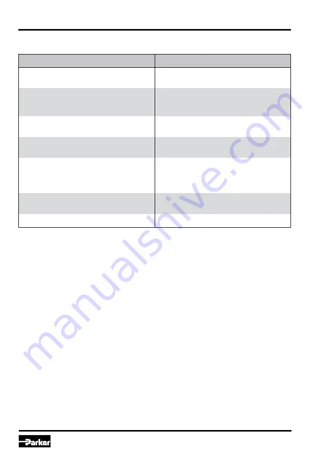
The table below gives information, which approaches may be embarked if typical problems with veloc-
ity control loops appear.
Problem
Solution
Variation error too large, when velocity
command remains constant
Use parameter
P17 = I-gain
(only effective for P26 >0)
Repeatable deviation by using a valve
with overlap/hysteresis
Use dead band compensation feature
P7 = MIN channel A
resp.
P8 = MIN channel B
Following error too large during
velocity profile execution
Use parameter
P13 = bypass gain
Slow, small amplitude oscillation
during constant velocity
Use integrator window
P26 = window I-gain
Disappointingly low P-gain
Check the frequency response of valve
and position transducer, the drive resonant
frequency and the feedback value processing
(s. items below)
Response too slow
Be sure
P16 = p-gain
is adjusted high
enough (s. also previous items)
In explainable problems
Check the setting of all parameters
Repeatable velocity errors due to valve dead
band or hysteresis
You can use the integrated dead band compensa-
tion coefficient to compensate for this. There are
separate adjustable parameters P7 and P8 for both
valve sides. This feature generates constant cor-
rection signals which will be active for the dedicat-
ed valve site if a signal occurs on the command
signal input. As a result this will cause the valve
to “Jump through“ the overlap region of the spool.
Increasing load stiffness
“Load stiffness” is the term for the resistance of
the servo loop to drive deflection by external forc-
es. Adjusting P16 to the highest practical value is
important.
Disappointing control loop function
The higher the value of the P-gain that can be used,
will result in better static and dynamic performance
of the system. You may not have any direct need for
fast response, but may still need a high value of P
Содержание PID00A-40 Series
Страница 44: ......


