background image


K3.1.141e Manual NitroFlow HP_EN.doc                           


                                - 27 - 


Table 5-2: Inputs and outputs 

 
When connecting input and output signals use a double insulated and shielded 
cable. 


5.8.1  Connect external device for remote control 

When selected YES at the remote option (refer to §6.2.6), a voltage free relay 
contact or switch needs to be connected to the digital input (ID1) on the printed 
circuit board.  

Clamp Function 

Input/output signals 

ID1 Remote 

start/stop 

Digital input 

Nominal input current: 10 mA 
Voltage:  internal power supply 

UA1 Outlet 

pressure 

UA2 Oxygen 

concentration 

Analogue outputs 

4 – 20 mA. Max. 200 Ohm 

K5 

Generator is producing nitrogen (RUN) 

K6 General 

alarm 

K7 No 

alarms 

K8 

Buzzer is activated by alarm 

Digital outputs 

Potential free relay contacts 
(normally open / normally closed) 
Max. 48V, 1A 

Содержание NitroFlow HP

Страница 1: ...w HP_EN doc 1 USER MANUAL NitroFlow HP NITROGEN GENERATOR Parker Filtration Separation B V PO Box 258 4870 AG Etten Leur The Netherlands Tel 31 0 76 508 53 00 Fax 31 0 76 508 53 33 E mail pfsinfo park...

Страница 2: ...g the customer The contents of this manual can also be changed without prior warning This manual is valid for the NitroFlow HP in its standard version Parker Filtration Separation B V can therefore no...

Страница 3: ...PARTS NITROFLOW HP 13 3 4 PROCESS DIAGRAM 14 3 5 PROCESS SCHEME 15 4 TECHNICAL SPECIFICATIONS 16 4 1 GENERAL 16 4 2 PRODUCTION CAPACITY 19 4 2 1 AIR CONSUMPTION 20 4 3 MAINTENANCE KIT 20 4 4 EXPANSION...

Страница 4: ...ING THE NITROFLOW HP 43 7 2 START NITROFLOW HP 43 7 3 STOP NITROFLOW HP 43 7 3 1 Alarm messages 44 8 TROUBLESHOOTING 45 8 1 TROUBLESHOOTING LIST 45 9 MAINTENANCE 47 9 1 MAINTENANCE SCHEME 47 9 2 REPLA...

Страница 5: ...l void the safety certification of this product If you have any questions or concerns please call your local representative or the technical services department Europe 44 1622 7233 00 USA 1 800 343 40...

Страница 6: ...aution shows a danger that can cause damage to the equipment Follow the instructions Electricity High voltage danger of electric shock Warning Risk for death due to suffocation Risk of fire Oxygen enr...

Страница 7: ...age Court Hermitage Lane Maidstone Kent ME16 9NT England Tel 44 1622 7233 00 Fax 44 1622 7287 03 1 4 Certificates The NitroFlow HP meets with the following requirements Subject Applicable standard Dir...

Страница 8: ...l trained personnel are allowed to work on the NitroFlow HP The user must be aware of hazards related to operating the NitroFlow HP and processes connected to the NitroFlow HP The user is responsible...

Страница 9: ...to work on electric and pneumatic equipment are allowed to do the installation maintenance and repairs Unqualified people are not allowed to repair the equipment Refer to 1 6 Lift the NitroFlow HP wit...

Страница 10: ...room where the enriched oxygen is ventilated or vent the enriched air outside Only feed the NitroFlow HP with air Keep the air feed to the NitroFlow HP clean and free of organic solvent vapors and oth...

Страница 11: ...ecyclable Optimal installation according to instructions and according to good craftsmanship will result in minimal energy consumption and maximal life of your system According to EC regulations elect...

Страница 12: ...A F S H2O H2 O2 N2 B C Fig 3 1 Separation principle A Pressurized air inlet B Hollow fibre membrane C Nitrogen outlet F Fast permeation S Slow permeation Ambient air contains nitrogen 78 1 oxygen 20...

Страница 13: ...Oxygen sensor B Hollow fiber membrane C Compressed air filters D SD card E Printed circuit board F Active carbon adsorber G Flow control valve for purity adjustment H Flow control valve for sample fl...

Страница 14: ...ow HP can either be connected directly to the nitrogen consumer or to a nitrogen reservoir The latter is advised in case of discontinuous or variable peak demands Fig 3 3 Installation lay out NitroFlo...

Страница 15: ...valve PI1 2 Pressure indicator F01 Coarse filter F02 Fine filter C1 Carbon adsorber F03 Dust filter QIA h Oxygen analyser FCV1 Flow control valve for purity adjustment FCV3 Flow control valve for sam...

Страница 16: ...ized air specifications Max feed pressure 13 bar g 190 psig Compressed air temperature range 10 50 C 50 120 F Pressure dew point 5 C 41 F Residual oil content 3 0 mg m3 Dimensions and connections Dime...

Страница 17: ...K3 1 141e Manual NitroFlow HP_EN doc 17 Parts NitroFlow HP 1x NitroFlow HP 1x Manual Table 4 1 General data...

Страница 18: ...h Active No Unit stop No Level 5 Delay 30 sec Alarm settings O2 low Active No Unit stop No Level 0 5 Delay 30 sec Alarm settings Inlet pressure high Active No Unit stop No Level 13 bar g Delay 30 sec...

Страница 19: ...HP1 159 004032 NitroFlow HP2 159 004033 NitroFlow HP3 159 004034 Table 4 3 Part numbers NitroFlow HP 4 2 Production capacity Type Nominal product capacity Nm hr Nitrogen purity 99 5 99 98 97 96 95 Nit...

Страница 20: ...ir use NitroFlow HP Nm3 hr 20 C 1013mbar at nominal conditions Feed pressure at inlet 7 bar g 100 psig Ambient temperature 20 C 68 F Ambient pressure 1013 mbar a 4 3 Maintenance kit Part part number M...

Страница 21: ...ions of personnel refer to 2 1 The NitroFlow HP must be transported and stored within a temperature range between 25 C and 50 C 5 2 Define location Install the NitroFlow HP on a fixed location The loc...

Страница 22: ...essed air 5 C 41 F 2 System has sufficient capacity 3 System can produce the required pressure take pressure drop into consideration Checklist when connecting to a dedicated stand alone compressor A c...

Страница 23: ...er contaminants and cannot be disposed to the sewer as such 5 6 Connecting to mains electricity Warning Do not connect the NitroFlow HP to the mains electricity with a wall plug as to prevent incorrec...

Страница 24: ...K3 1 141e Manual NitroFlow HP_EN doc 24 Fig 5 3 Terminals NitroFlow HP Refer to fig 5 4 for location of power cable inlet N L1 PE N L1 PE...

Страница 25: ...ompressed inlet air must be within 10 C 50 F and 50 C 120 F refer to table 4 1 Nitrogen outlet Connect nitrogen outlet to the application or to the reservoir refer to fig 3 3 Oxygen outlet The outlet...

Страница 26: ...t contacts In and output signals can be connected to the terminal strip on the printed circuit board refer to 3 3 Fig 5 5 Printed circuit board Terminal strip K5 K6 K7 K8 UA1 UA2 ID1 PI1 PI2 TI TT QAI...

Страница 27: ...r switch needs to be connected to the digital input ID1 on the printed circuit board Clamp Function Input output signals ID1 Remote start stop Digital input Nominal input current 10 mA Voltage interna...

Страница 28: ...by pushing the return to previous screen button 6 2 Configure software parameters 6 2 1 Main screen Access This is the start up screen that automatically appears when the generator is switched on Fun...

Страница 29: ...tart if it was stopped less then 3 minutes ago Remaining time is shown on the display When the generator was stopped longer then 3 minutes ago it will start immediately once pressing the start stop bu...

Страница 30: ...enus Symbol Menu Access to log on menu refer to 6 2 3 Access to alarm settings menu refer to 6 2 4 Access to pressure switch menu refer to 6 2 5 Access to options menu refer to 6 2 6 Access to local s...

Страница 31: ...6 2 6 After selecting PINCODE YES the default pin code 1234 Select PIN CODE CHANGE if you want to enter your personal pin code In case you forgot your personal pin code enter pin code 7833 to return...

Страница 32: ...d Correct pin code has to be entered to have access to menus 6 2 4 Alarm menu Access Touch alarm menu button in settings screen Function Set various alarms The alarms that can be set are Screen Alarm...

Страница 33: ...w HP_EN doc 33 To activate an alarm touch the active button A You can select NO YES or AUTO RESET When you select YES or AUTO RESET the rest of the data that needs to be set for the specific alarm wil...

Страница 34: ...at which the alarm will appear Level screen 3 6 4 6 0 189 PSIG Inlet pressure level at which the alarm will appear Level screen 5 6 6 6 0 11 BAR G Outlet pressure level at which the alarm will appear...

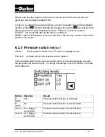
Страница 35: ...sound will stop This can only be done if the actual problem was solved 6 2 5 Pressure switch menu Access Touch pressure switch menu button in settings screen Function Activate and set the pressure sw...

Страница 36: ...external device has to be a voltage free switch or relay contact Unit can now be started from a remote location by closing the contact switch By opening the contact switch the unit will be stopped If...

Страница 37: ...All text in the screen will appear in the chosen language Pressure B BAR G PSIG Pressure indications will appear in the chosen setting If BAR G is chosen then temperature will be automatically in C I...

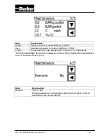
Страница 38: ...onsists of 5 different screens Each screen displays maintenance status or calibration buttons Data Explanation Type Shows type of generator Version Software version of system O2 lifetime Month year wh...

Страница 39: ...her BAR G or PSIG C Inlet Compressed air inlet temperature in Celcius or Fahrenheit When selected BAR G temperature is displayed in Celcius When selected PSIG temperature is shown in Fahrenheit Refer...

Страница 40: ...flow by entering flow value measured with external flow meter Replace Filter When a filter has been replaced during maintenance button can be touched and countdown for the new filter is set System ask...

Страница 41: ...nly alarms Alarms as well as status of the sensors temperature pressure O2 flow and maintenance are saved on the SD card The time between the logging saving of this data on the memory card can be chos...

Страница 42: ...r for this software Your PC also needs a SD card reader 1 Switch off the generator 2 Remove the SD card refer to 3 3 3 Refer to appendix A for information how to use the NitroView software 4 Replace t...

Страница 43: ...vel and vice versa The oxygen level can be read on the display refer to 3 3 7 Check whether the system works according to the settings of the control system 8 Close all sheet metal covers Important Th...

Страница 44: ...utlet high Outlet pressure too high Off P outlet low Outlet pressure too low Off T inlet high Inlet temperature too high On T inlet low Inlet temperature too low On P Inlet sensor fail Inlet pressure...

Страница 45: ...ting Sample flow to O2 sensor is too low Check readjust the sample flow to the O2 sensor Refer to 9 5 Nitrogen outlet line is restricted Check open the outlet line Delivery flow of nitrogen too low Fa...

Страница 46: ...low to the O2 sensor Refer to 9 5 O2 sensor drifted Calibrate O2 sensor Refer to 9 5 Required O2 concentration can not be reached O2 sensor used up Replace O2 sensor Refer to 9 4 Switch off pressure s...

Страница 47: ...8000 running hours which comes first Active carbon adsorber Replace adsorber 1x per year together with filter elements Check purity setting Determine oxygen content in output and readjust by readjust...

Страница 48: ...at the filter is depressurized 6 Turn the filter bowl D clockwise and pull the bowl from the filter housing A 7 Unscrew the blue knob C 8 Remove the old filter element B 9 Place a new filter element B...

Страница 49: ...leakages after restarting NitroFlow HP 9 4 Replace oxygen sensor 1 Stop and switch off the NitroFlow HP 2 Remove the cover plate above inlet and outlet connections of the NitroFlow HP 3 Disconnect co...

Страница 50: ...wait until the oxygen level has stabilized this will take approx 60 seconds 5 Go to screen 5 5 and touch O2 20 9 span button The system will ask for confirmation select YES 6 Start the NitroFlow HP b...

Страница 51: ...1 Stop the unit by touching the button in the main screen refer to 6 2 1 2 Switch off the main switch 3 Remove the cover plate above inlet and outlet connections 4 Remove the fuse holder A 5 Place a...

Страница 52: ...K3 1 141e Manual NitroFlow HP_EN doc 52 10 Electrical scheme and terminal connections Fig 10 1 Electrical scheme NitroFlow HP...

Страница 53: ...K3 1 141e Manual NitroFlow HP_EN doc 53 Fig 10 2 Electrical terminal connections NitroFlow HP...

Страница 54: ...et filter 48 Installation 21 L Liability 8 Local settings menu 37 Location 21 Log on menu 31 M Main screen 28 Maintenance 47 Maintenance kit 20 Maintenance menu 38 Menu structure 28 N Nitrogen 9 nitro...

Страница 55: ...be found on this bar There are 2 menus File main menu and about 2 System info Info about the log you are viewing Info about the hardware the log came from 3 View options Enable extra columns of the lo...

Страница 56: ...the type of log see Preferences When selecting a line the alarms will be showed on the bottom of the screen 8 8 Alarm bar This bar shows alarm states of the selected log When you ve selected a log th...

Страница 57: ...or as well For example if you use dark colors for the events you can choose white text Just click on a color box then you can pick a color 3 Default colors Click this to reset all colors back to defau...

Страница 58: ...4 Remove the file FORCE txt when present 5 Place the SD card in the controller 6 Switch the main Power switch ON 7 The IO board is now upgrading 30sec 8 The message initialisation pops up 60sec 9 The...

Страница 59: ...nu functionality improved Compressor hour counter reset code added V2 0 03 December 2007 New version because of hardware changes Service messages no buzzer Filter lifetime counter adjusted Data log me...

Отзывы: