


Parker EME
Installation of a single axis
192-510201N1 HLR 2019-04
21
3.2
Installation of a single axis
Linear actuators must be sufficiently fastened to the surrounding
construction/substructure. Not sufficiently fastened linear actuators may shift,
slide and may cause considerable damage and injuries.
Do only use the appropriate mounting parts mentioned in the installation
instructions for the respective mounting methods. The torque moments
mentioned below are mandatory.
Requirements for substructzre devices
Bends or deformations on the linear axis due to excessive loads / weights, too
large support distances or uneven substructure devices should be avoided as
much as possible. Substructure which do not meet the requirements may cause
internal tension to the linear actuators and the guiding system. This may reduce
expected service life of linear actuators.
The HLR linear axis should be supported as consistently as possible on leveled or
machined connection surfaces:
Flatness of the connection surfaces:
≤
0.2 mm/m
permissible max. bend deflection of the axis: see HLR catalogue
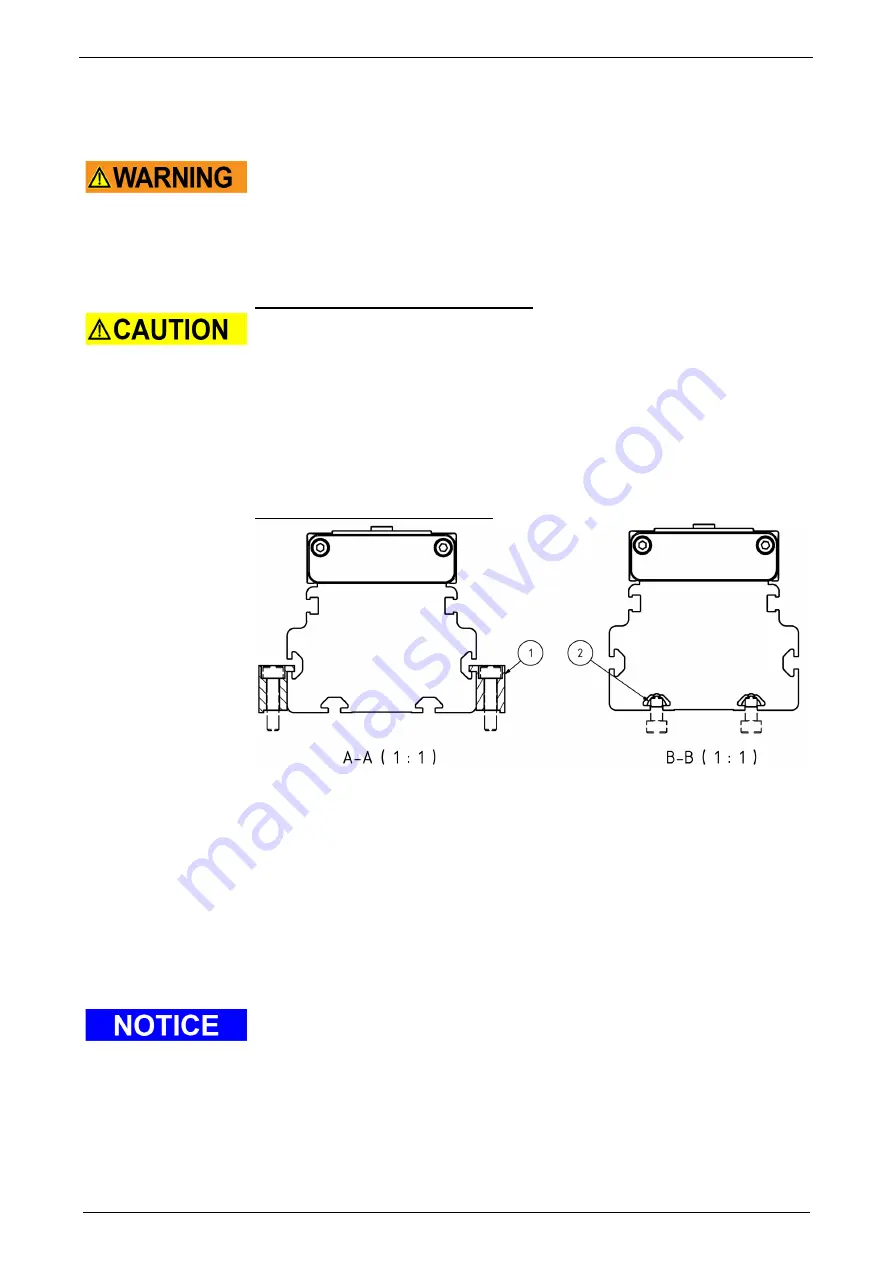
Connection options for mounting
Figure 1: installation options
To fasten the linear axis to the substructure device, one groove is provided on
each side of the support profile and two grooves on the underside.
For the installation of the lateral grovves, two toe clamps are optionally available
(please refer to Figure 1, Pos. 1). For the installation of the grovves on the
underside, two slot nuts are optionally available (please refer to Figure 1, Pos. 2
Please refer to accessories in the HLR catalogue.
The linear actuator must be fixed at at least two points along the carrier profile.
Additional mounting points are recommended for linear actuators with longer
stroke lengths and high loads.
Either two toe clamps (left and right on the carrier profile) or 4 slot nuts (two for
each lower groove) are required for each fastening point, see Figure 1.
For dimensions of the HLR linear actuator, hole pattern of the mounting options
and recommended support distances, see HLR catalogue.
Depending on installation conditions and space conditions in the plant, it may be
more advantageous to mount the drive to the linear actuator before installation; see
chapter installation/ dismantelling of the drive (see page 27).
Installation of a single axis
Содержание HLR Series
Страница 6: ...Introduction HLR Mounting Instruction 6 192 510201N1 HLR 2019 04 1 3 Mounting explanation...
Страница 14: ...Device description HLR Mounting Instruction 14 192 510201N1 HLR 2019 04...
Страница 15: ...Parker EME Conditions of utilization 192 510201N1 HLR 2019 04 15...
Страница 16: ...Device description HLR Mounting Instruction 16 192 510201N1 HLR 2019 04 2 1 Technical data...
Страница 17: ...Parker EME Dimensions 192 510201N1 HLR 2019 04 17 2 2 Dimensions...
Страница 18: ...Device description HLR Mounting Instruction 18 192 510201N1 HLR 2019 04...
Страница 19: ...Parker EME Dimensions 192 510201N1 HLR 2019 04 19...
Страница 54: ...Index HLR Mounting Instruction 54 192 510201N1 HLR 2019 04...
Страница 55: ...Parker EME Spare and Wear Parts 192 510201N1 HLR 2019 04 55...
Страница 56: ...Index HLR Mounting Instruction 56 192 510201N1 HLR 2019 04...


