INSTALLATION • OEM650/OEM650X
28
typical configuration of this output.
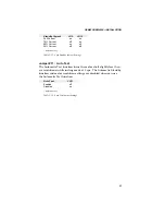
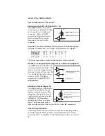
Sequence Inputs #1 - #3 (Signals 11 - 13)
The OEM650X has three dedi-
cated sequence inputs that allow
you to control seven different
sequences. Refer to the
X
commands for information on
how to control these inputs.
Sequence #Ø is not a valid
sequence.
Sequences are executed remotely by using one of the following logic
patterns. (1 represents a +5V signal, Ø represents a ØV signal.)
Sequence #
Ø
1
2
3
4
5
6
7
SEQ Input #1
Ø
1
Ø
1
Ø
1
Ø
1
SEQ Input #2
Ø
Ø
1
1
Ø
Ø
1
1
SEQ Input #3
Ø
Ø
Ø
Ø
1
1
1
1
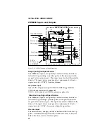
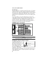
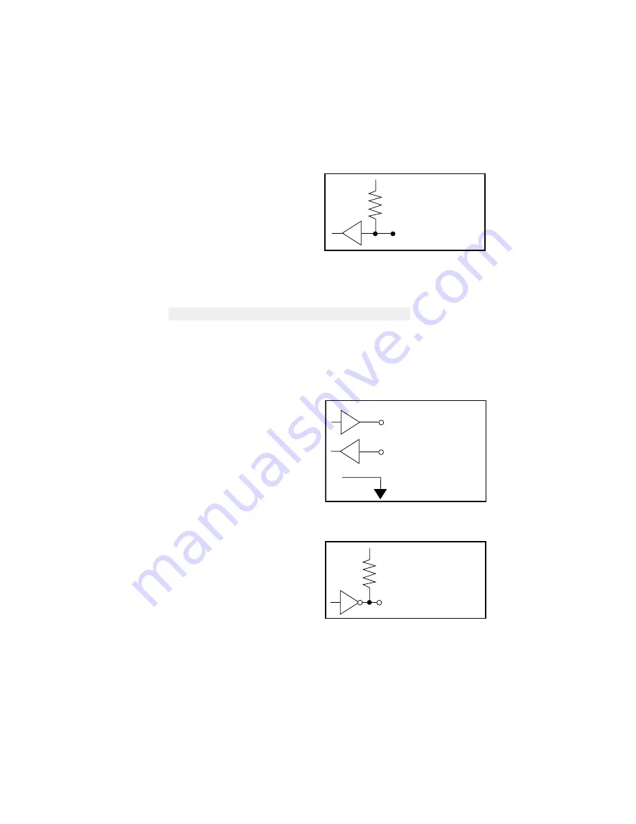
The figure represents a typical configuration of these outputs.
RS-232C—Tx (Signal 14), Rx (Signal 15), and Ground (Signal 7)
The OEM650X uses RS-232C as
its communication medium. This
indexer does not support hand-
shaking. A typical three-wire (Rx,
Tx, and Signal Ground) configu-
ration is used). The figure
represents a typical RS-232C
configuration.
Shutdown Output (Signal 16)
The OEM produces a Shutdown
output that is identical to the
indexer's internal signal. This
output may be used to slave to
another drive or to monitor the
OEM650X. The Shutdown
output's default state is logic
high. The figure represents a
typical configuration of this output. (Refer to the
ST
command.)
Closed Loop Operation
Closed loop moves require an external encoder to provide position
correction signals. Motor position may be adjusted to reach the
desired position. To implement the closed loop functions, you must
• Maximum low-level input: 0.8V
(Sinks 1.2 mA)
• Minimum high-level input: 2V
+5V
4.75k
HCT244
• Meets EIA RS-232C & CCITT
V.28 specifications
Rx
Tx
•Signal ground
• Minimum high-level output: 4.26V
(Source -24mA)
• Maximum low-level output: 0.44V
(Sinks @ 23 mA)
+5V
10k
ACTØ4
Содержание Compumotor OEM350
Страница 7: ...OVERVIEW OEM650 OEM650X vi ...
Страница 55: ...TROUBLESHOOTING OEM650 OEM650X 48 ...

