background image

5

OEM650/OEM650X • INSTALLATION

WARNING

The drive and motor should be mounted to a heatsink.  Drive mounting does not affect

the following tests, but if you operate the OEM650/OEM650X for extended periods

without proper mounting, it will damage the drive and/or motor.  When you complete

the quick tests, remove power to the drive.

Perform installation and test procedures in a properly grounded
environment.  Compumotor recommends the use of a grounding
strap.

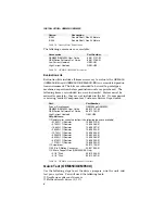
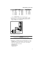
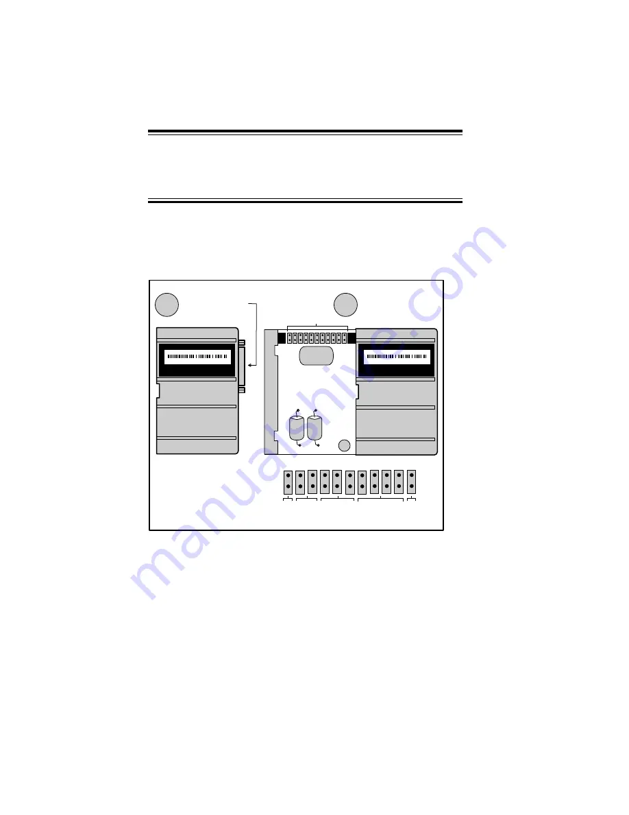
1. Remove the cover by applying pressure to the 25-pin D connector.

To remove cover, 
push the 25-pin D 
connector in while 
holding the sides of 
the unit.

11

10

9

8

7

6

5

4

3

2

1

Jumpers

A

When the cover is 
removed, the 
jumpers will be 
visible at the upper 
portion of the unit.

B

Auto

Test

Auto

Standby

Motor

Waveform

Shape

Motor

Resolution

Motor

Current

Range

Enlarged view of jumpers

Compumotor

5500 Business Park Dr.
Rohnert Park, CA  94928

Prod:  Ø571Ø2-2-6-Ø17-Ø1Ø

Made In USA

Compumotor

5500 Business Park Dr.
Rohnert Park, CA  94928

Made In USA

Prod:  Ø571Ø2-2-6-Ø17-Ø1Ø

Figure 2-1.  OEM650/OEM650X Jumpers

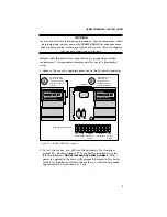
2. To test the system, you will use the Automatic Test function,

jumper 

11

.


Remove jumper 

11


to enable the function (save for

later installation). 

Do not remove any other jumpers

.  When

power is applied to the drive with jumper 

11

 removed, the Auto-

matic Test function will rotate the motor in an Alternating mode
approximately 6 revolutions at 1 rps.

Содержание Compumotor OEM350

Страница 1: ...0 OEM350X Drive and Drive Indexer User Guide Compumotor Division Parker Hannifin Corporation p n 88 013157 02 A REMOTE REF CURRENT DUMP VDC VDC A A B B Compumotor OEM OEM s e r i e s D R I V E D R I V E DRI V E D R I V E POWER FAULT ...

Страница 2: ... never touch them while they are in operation High voltages exist with in enclosed units on rack system backplanes and on transformer terminals KEEP CLEAR of these areas when power is applied to the equipment Parker Compumotor constantly strives to improve all of its products We reserve the right to modify equipment and user guides without prior notice No part of this user guide may be reproduced ...

Страница 3: ...ange 19 Jumpers 2 5 Motor Resolution 19 Jumpers 6 8 Motor Waveform Shape 20 Jumpers 9 10 Auto Standby 20 Jumper 11 Auto Test 21 Motor Mounting 22 Attaching the Load 22 Couplings 23 OEM650 Inputs and Outputs 24 Step Input Signal Specification 24 Direction Input Signal Specification 24 OEM650X Inputs and Outputs 26 Step Signal 1 Direction Signal 2 Outputs 26 CW Signal 3 CCW Signal 4 Limit Inputs 27 ...

Страница 4: ...e to the Motor 35 Motor Waveforms 35 Performance Specifications 36 Accuracy 36 Repeatability 36 Hysteresis 36 Rotor Inertia 36 Motor Performance 36 4 Troubleshooting 41 Chapter Objectives 41 Drive Maintenance 41 Motor Maintenance 41 Problem Isolation 41 Front Panel LEDs 42 Common Problems and Solutions 42 Testing the Motor 45 RS 232C Problems 45 Software Debugging Tips 46 Returning the System 46 I...

Страница 5: ...tion of this chapter your system should be completely installed and ready to perform basic operations Chapter 3 Tuning Specifications This chapter contains information on system performance specifica tions speed torque curves environmental specifications etc Tuning procedures that are designed to help you operate your system at peak performance are also provided Chapter 4 Troubleshooting This chap...

Страница 6: ... features carefully read Chapter 2 6 After you have read Chapter 2 and clearly understand what must be done to properly install the system begin the installation process Do not deviate from the instructions provided 7 Before you customize your system check all of the system func tions and features to ensure that you have completed the installa tion process correctly The successful completion of th...

Страница 7: ...OVERVIEW OEM650 OEM650X vi ...

Страница 8: ... package while providing short circuit protection The OEM650 is compatible with all Compumotor indexers The mechanical design is a fully enclosed product that uses a heatplate technique to provide a heat dissipation path The user must attach the OEM650 module to a suitable mounting surface OEM650X Description The OEM650X Drive Indexer is the same drive product as the OEM650 but it includes an inde...

Страница 9: ...th motors whose inductance is in the 10 mH to 80 mH range The OEM650 OEM650X provides the following features Microprocessor controlled microstepping provides smooth opera tion over a wide range of speeds Full short circuit protection for phase to phase and phase to ground short circuits Motor regeneration protection Over temperature protection Uses low inductance motors for improved high speed per...

Страница 10: ...M650 or drive indexer OEM650X Compare your order with the units shipped Part Part Number OEM Microstepping Drive OEM650 OEM Microstepping Drive Indexer OEM650X Table 2 1 OEM650 Drive OEM650X Drive Indexer The following options may be used with the OEM650X Option Description M2 Nonvolatile Memory 2k BBRAM Table 2 2 OEM650X Options The following motor s may be used with the OEM650 and OEM650X Compar...

Страница 11: ...t is missing contact Compumotor s Customer Service Department Part Part Number Drive or Drive Indexer OEM650 or OEM650X OEM650 OEM650X User Guide 88 013157 02 OEM Series Software Ref Guide 88 013785 01 High Current Heatsink OEM HS2 Ship kit Items Resistors for current selection the following types are available 21 0KΩ 1 Resistor 12 008319 01 5 76KΩ 1 Resistor 12 008265 01 15 8KΩ 1 Resistor 12 0083...

Страница 12: ...e unit 11 10 9 8 7 6 5 4 3 2 1 Jumpers A When the cover is removed the jumpers will be visible at the upper portion of the unit B Auto Test Auto Standby Motor Waveform Shape Motor Resolution Motor Current Range Enlarged view of jumpers Compumotor 5500 Business Park Dr Rohnert Park CA 94928 Prod Ø571Ø2 2 6 Ø17 Ø1Ø Made In USA Compumotor 5500 Business Park Dr Rohnert Park CA 94928 Made In USA Prod Ø...

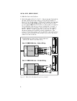
Страница 13: ...ause the drive to dissipate slightly more heat than a serial configuration This increase in drive temperature will not affect the unit s performance but it may adversely affect heat sensitive devices that are stored within the same enclosure RED BLUE GREEN ORANGE YELLOW BLACK BROWN WHITE Top View RED BLUE GREEN ORANGE YELLOW BLACK BROWN WHITE Top View A B A B OEM s e r i e s REMOTE REF CURRENT DUM...

Страница 14: ... GREEN B RED A WHITE B OEM s e r i e s REMOTE REF CURRENT DUMP VDC VDC A A B B POWER FAULT Size 34 OEM Series Motors Parallel Wiring Figure 2 3 NEMA 34 Size OEM Motor Wiring Series 5 Set motor current Table 2 7 contains the proper motor current settings for Compumotor OEM motors A 1 4 watt resistor connected between REF and CURRENT sets motor current Adjust the drive current to match the motor tha...

Страница 15: ...e 2 5 to 7 5 amps When jumper 1 is removed the drive can generate 0 83 to 2 5 amps If you use the OEM350 OEM350X use Table 2 9 for resistor and current values to use with high inductance 10 mH to 80 mH low current motors Jumper 1 Installed Jumper 1 Removed Current Resistance Current Resistance Current Resistance Amps Ohms Amps Ohms Amps Ohms 7 5 0 Ω 4 9 7 32 kΩ 2 5 0 Ω 7 4 205 Ω 4 8 7 68 kΩ 2 4 61...

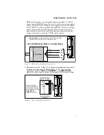
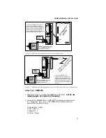
Страница 16: ... 24VDC 75VDC power supply to VDC and VDC Refer to Figure 2 5 for a diagram of this connection and the complete OEM650 test configuration OEM s e r i e s REMOTE REF CURRENT DUMP VDC VDC A A B B POWER FAULT Power Supply Refer to Figures 2 2 and 2 3 for specific motor wiring instructions OEM Series Motor Figure 2 5 OEM650 Test Configuration WARNING Reversing VDC and VDC can seriously damage the drive...

Страница 17: ...4 Using the indexer send step pulses to the drive that will rotate the motor one CW revolution 25 000 step pulses at 1 rps 25 000 steps per second 5 Using the indexer send step pulses to the drive that will rotate the motor one CCW revolution at 1 rps The drive s default direction is CCW i e if the the direction input is not activated the motor will rotate CCW if the direction input is activated t...

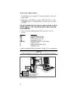
Страница 18: ...OWER FAULT Power Supply Refer to Figures 2 2 and 2 3 for specific motor wiring instructions OEM Series Motor To connect the OEM650 to a non Compumotor indexer or pulse generator use the pinouts of the OEM650 s 25 pin D connector as shown in this figure Refer to the indexer or pulse generator s user guide for any specific instructions associated with the device 1 Step 2 Direction 14 Step 15 Directi...

Страница 19: ...t the system Command Description MN Sets unit to Normal mode LD3 Disables CW CCW Limits A1Ø Set acceleration to 10 rps2 V1Ø Set velocity to 10 rps D25ØØØ Set move distance to 1 CW revolution G Initiate move Go H Reverse move direction CCW G Initiate move Go 5 After verifying that the motor moves CW and CCW turn off power CAUTION RS 232C signals are not on pins 2 3 and 7 on the 25 pin D connector O...

Страница 20: ...4 650 0 175 1 000 7 000 Mounting Clearance 1 000 2 000 Mtg Clearance 2x 0 177 Thru Clearance for 8 PHP Screw 1 625 0 812 0 335 Compumotor 5500 Business Park Dr Rohnert Park CA 94928 Exposed aluminum for electrical grounding This surface must be thermally coupled to a cold plate in most applications Compumotor OEM s e r i e s D R I V E D R I V E D R I V E DRIVE REMOTE REF CURRENT DUMP VDC VDC A A B...

Страница 21: ...s REMOTE REF CURRENT DUMP VDC VDC A A B B POWER FAULT OEM s e r i e s REMOTE REF CURRENT DUMP VDC VDC A A B B POWER FAULT OEM s e r i e s REMOTE REF CURRENT DUMP VDC VDC A A B B POWER FAULT 0 375 4 65 2 35 2 Minimum 2 Figure 2 10 OEM650 OEM650X Without a Heatsink Figure 2 11 shows the heat generated by the OEM650 OEM650X that needs to be dissipated by the mounting surface The OEM uses a heatplate ...

Страница 22: ...re protected The drive will shut down if its heatplate temperature exceeds 58 C 136 F To measure drive temperature under operating conditions position a thermal probe on the left edge of the heatplate approximately 1 5 from the top of the drive as shown in Figure 2 12 Compumotor OEM OEM s e r Measure heatplate temperature on left side 1 5 from top of drive Figure 2 12 Heatplate Temperature Measure...

Страница 23: ... to the OEM HS1 heatsink Use a star washer on the bottom screw to ensure proper electrical grounding Two 8 screws should be used to mount the OEM HS1 to the cabinet heatsink Do not use a star washer between the back of the OEM or heatplate and the mounting surface The mounting surface must be flat Use thermal grease or thermal pads to facilitate heat transfer from the drive s heatplate to your mou...

Страница 24: ...OEM s e r i e s REMOTE REF CURRENT DUMP VDC VDC A A B B POWER FAULT OEM s e r i e s REMOTE REF CURRENT DUMP VDC VDC A A B B POWER FAULT OEM s e r i e s REMOTE REF CURRENT DUMP VDC VDC A A B B POWER FAULT OEM s e r i e s REMOTE REF CURRENT DUMP VDC VDC A A B B POWER FAULT 0 5 4 65 2 35 2 2 5 Minimum Figure 2 14 OEM650 OEM650X OEM HS1 Minimum Area Panel Layout Panel layout for minimum depth is shown...

Страница 25: ...erature below 55 C This heatsink may be purchased as an option to provide adequate drive cooling when adequate cooling cannot otherwise be achieved refer to Figures 2 16 and 2 17 Secure the drive or drive indexer to the heatsink with 8 screws Use thermal grease or a thermal pad between the unit and the heatsink to facilitate heat transfer Secure the drive and heat sink to your mounting surface wit...

Страница 26: ... shows the location and function of the 11 OEM650 OEM650X jumpers When the unit is shipped to you all 11 jumpers are installed Each jumper s function is defined in this section Jumper 1 Motor Current Range This jumper sets the range of user configurable motor current settings Refer to Tables 2 8 and 2 9 for motor current values with jumper 1 installed and removed Jumpers 2 5 Motor Resolution These...

Страница 27: ...y Jumpers 6 8 Motor Waveform Shape These jumpers control the shape or waveform of the commanded motor current Motor waveforms can reduce resonance problems and allow the motor to run smoothly This function will not operate when the 200 step or 400 step motor resolutions are used Motor Waveform JU6 JU7 JU8 Pure sine off off on 2 3rd Harmonic off on off 4 3rd Harmonic on on on 4 3rd Harmonic off off...

Страница 28: ...Standby Jumper Settings Jumper 11 Auto Test The Automatic Test function turns the motor shaft slightly less than six revolutions in Alternating mode at 1 rps The Automatic Standby function and motor resolution settings are disabled when you use the Automatic Test function Auto Test JU11 Enabled off Disabled on Default Setting Table 2 13 Auto Test Jumper Settings ...

Страница 29: ...tatic loads of the same magnitude The motor under certain profiles can produce low frequency vibrations in the mount ing structure These vibrations can cause metal fatigue in structural members if harmonic resonances are induced by the move profiles you are using A mechanical engineer should check the machine design to ensure that the mounting structure is adequate CAUTION Consult a Compumotor App...

Страница 30: ...x coupling is used one and only one of the shafts must be free to move in the radial direction without constraint Do not use a double flex coupling in this situation it will allow too much freedom and the shaft will rotate eccentrically which will cause large vibrations and immediate failure Double Flex Coupling Use a double flexed coupling whenever two shafts are joined that are fixed in the radi...

Страница 31: ...ut This input may also be differentially driven The input driver must provide a minimum of 6 5 mA approximately 3 5 VDC 15 mA maximum Step Pulse Input Operate the step pulse input within the following guidelines 200 nanosecond pulse minimum 40 60 duty cycle 2 MHz maximum pulse rate Direction Input Signal Specification The OEM650 s inputs are optically isolated and may be driven activated by provid...

Страница 32: ... are shorted with the appropriate resistor A remote motor current value must be selected see Table 2 8 to set the operating current Identify the current resistor associated with the operating current you select Use the resistor values to determine the remote resistor that must be installed between the CURRENT and REMOTE terminals Use the following equation to detemine RREMOTE RREMOTE 13 300 3650 R...

Страница 33: ...1 2 3 4 5 6 8 9 10 11 12 13 14 15 19 18 21 20 23 22 25 24 N C N C N O N C N C N C CW Limit Step Output Direction Output CCW Limit Home Reserved GND Ref Output 2 Fault Output Output 1 Sequence 1 Sequence 2 Sequence 3 Shutdown Encoder Channel A Encoder Channel B Encoder Channel Z N C N C N C Trigger Input 1 Trigger Input 2 Trigger Input 3 N C N C N C Address Sel 1 Address Sel 2 Address Sel 3 RS 232C...

Страница 34: ...d Signal 6 This signal cannot currently be used to perform any function in this release of the OEM650X Additional functionality may be provided in future revisions Output 1 Signal 10 and Output 2 Signal 8 The OEM650X has two dedicated programmable outputs They may be used to signal peripheral devices upon the start or comple tion of a move The default state for Outputs 1 and 2 is logic low The fig...

Страница 35: ...not support hand shaking A typical three wire Rx Tx and Signal Ground configu ration is used The figure represents a typical RS 232C configuration Shutdown Output Signal 16 The OEM produces a Shutdown output that is identical to the indexer s internal signal This output may be used to slave to another drive or to monitor the OEM650X The Shutdown output s default state is logic high The figure repr...

Страница 36: ...50X s trigger function The figure represents a typical configuration of these inputs Address Signals 1 3 Signals 23 25 The OEM650X has three dedicated address inputs that allow you to specify a unique address for each OEM650X in your configuration Units may be assigned a valid address from 1 to 8 Each unit in the configuration must have a unique address The default address is 8 all three inputs ar...

Страница 37: ...e drive to transmit information from the RS 232C port such as a status or report command must be prefixed with a device address This prevents daisy chained units from all transmitting at the same time Attach device identifiers to the front of the command The Go G command instructs all units on the daisy chain to go while 1G tells only unit 1 to go When you use a single communications port to contr...

Страница 38: ...ation P Parallel Configuration 34 size motors are internal wired in Parallel User must supply this level of wattage Table 2 14 Power Sizing Use the following equation to determine drive heat Drive Heat Watts 0 31 IM 2 1 13 IM 3 IM Motor Current Calculations To convert watts to horsepower divide by 746 To convert watts to BTU hour multiply by 3 413 To convert watts to BTU minute multiply by 0 0569 ...

Страница 39: ...an externally mounted power resistor The circuitry effectively closes a switch to ground when the power supply voltage exceeds 85VDC This switch terminal is at the screw termi nal labeled DUMP The power dump feature dissipates the energy created by a regenerative load 100 joules maximum The power dump is not designed to protect the unit from overvoltage caused by a poorly regulated or faulty power...

Страница 40: ...e resonance region The OEM650X s microstepping capability allows you to operate a motor smoothly at low speeds Motors that will not accelerate past 1 rps may be stalling due to resonance You can add inertia to the motor shaft by putting a drill chuck on the shaft The drill chuck may provide enough inertia to test the motor when it is not loaded In extreme cases a viscous damper may also be needed ...

Страница 41: ... The goal of this tuning method is to tune the motor for its lowest oscillation amplitude Sounding Board Method You can practice your tuning skills with an unloaded motor placed on a sounding board or table When you command a velocity that is near the motor s resonance speed the phenomenon will cause an audible vibration The goal of this tuning method is to tune the motor for the least amount of v...

Страница 42: ... Double the motor speed 2nd speed resonance until the motor runs rough again 4 Adjust offsets A and B again for best smoothness 5 Repeat above steps until no further improvement is noted Motor Waveforms Step motor manufacturers make every effort to design step motors that work well with sinusoidal current waveforms However due to physical limitations most motors operate best with a current wave fo...

Страница 43: ... 0 25 OEM83 62 MO 3 50 0 64 OEM83 93 MO 6 70 1 23 OEM83 135 MO 10 24 1 87 Table 3 2 Rotor Inertia OEM Series Motors Motor Performance The performance speed torque curves in this section show that different levels of performance can be achieved by wiring your motor in series or parallel and the power supply used to run the system Size 34 motors are internally wired in parallel and can only be opera...

Страница 44: ... 40 50 0 10 20 30 40 50 60 70 80 WATTS Shaft Power TORQUE OZ IN OEM650 OEM650X with OEM57 51 MOS 75VDC 3 3A SPEED RPS Torque 0 10 20 30 40 50 0 30 60 90 120 150 WATTS Shaft Power TORQUE OZ IN OEM650 OEM650X with OEM57 83 MOS 75VDC 3 8A SPEED RPS Torque ...

Страница 45: ...tion 0 10 20 30 40 50 0 5 10 15 20 25 30 35 40 WATTS Shaft Power TORQUE OZ IN OEM650 OEM650X with OEM57 40 MOP 38VDC 5 3A SPEED RPS Torque 0 10 20 30 40 50 0 10 20 30 40 50 60 70 80 WATTS Shaft Power TORQUE OZ IN OEM650 OEM650X with OEM57 51 MOP 38VDC 6 6A SPEED RPS Torque ...

Страница 46: ... 50 0 30 60 90 120 150 WATTS Shaft Power TORQUE OZ IN OEM650 OEM650X with OEM57 83 MOP 38VDC 7 5A SPEED RPS Torque OEM83 Motors 0 10 20 30 40 50 0 30 60 90 120 150 WATTS Shaft Power TORQUE OZ IN OEM650 OEM650X with OEM83 62 MO 75VDC 4 4A SPEED RPS Torque ...

Страница 47: ...50 0 50 100 150 200 250 WATTS Shaft Power TORQUE OZ IN OEM650 OEM650X with OEM83 93 MO 75VDC 5 6A SPEED RPS Torque 0 10 20 30 40 50 0 50 100 150 200 250 300 350 400 WATTS Shaft Power TORQUE OZ IN OEM650 OEM650X with OEM83 135 MO 75VDC 6 9A SPEED RPS Torque ...

Страница 48: ...ct the motor cable periodically for signs of wear This inspec tion interval is duty cycle environment and travel length dependent The cable should not have excessive tensile force applied to it and should not be bent beyond a one inch radius of curvature during normal operation Tighten all cable connectors Reducing Electrical Noise For detailed information on reducing electrical noise in your syst...

Страница 49: ...cessary steps to resolve it Use the solutions in this chapter If your system s problem persists call Compumotor at 800 358 9070 Front Panel LEDs There are two LEDs on the front panel of the OEM650 OEM650X refer to Figure 5 1 OEM s e r i e s REMOTE REF CURRENT DUMP VDC VDC A A B B POWER FAULT Green POWER LED Red FAULT LED Figure 5 1 OEM650 OEM650X LEDs The FAULT LED is red and turns on when the amp...

Страница 50: ...the current selector resistor with the current table measure the resistor with an ohmmeter Install Jumper 1 Double check the desired resistor value Remove 25 pin D connector to isolate the problem Check jumpers 9 and 10 The motor fault LED is on The motor is not connected A motor winding is open The drive has detected a short circuit in the motor wiring The drive is overheating The drive may have ...

Страница 51: ...d inertia to the motor shaft Verify that the motor is sized correctly for your application The motor unloaded stalls at nominal speed There is insufficient rotor inertia Mid frequency resonance Add inertia to the motor shaft Add a damper to the shaft Motor does not move commanded distance Motor resolution is set incorrectly Determine the resolution on your indexer and verify that the drive resolut...

Страница 52: ...ould be nearly identical 4 Use the ohmmeter to check the resistance between Phase A and Phase B It should be infinite 5 Use the ohmmeter to check the resistance between Phase A and Earth the motor case shaft It should be infinite 6 Use the ohmmeter to check the resistance between Phase B and Earth the motor case shaft It should be infinite 7 Turn the shaft manually There should not be any torque I...

Страница 53: ...on offers helpful tips for debugging programs and under standing errors and fault conditions The OEM650 OEM650X has several tools that you can use to debug a problem in the system The software tools are listed below RA Limit Switch Status Report R Report Status IS Input Status Report BS Buffer Status Report B Buffer Status Report Returning the System If your OEM650 OEM650X system is faulty you mus...

Страница 54: ... the system sizing speed acceleration duty cycle inertia torque friction etc What was the system environment temperature enclosure spacing unit orientation contaminants etc What upgrades are required hardware software user guide 3 Call Parker Compumotor s Applications Engineering Department 800 358 9070 for a Return Material Authorization RMA number Returned products cannot be accepted without an ...

Страница 55: ...TROUBLESHOOTING OEM650 OEM650X 48 ...

Страница 56: ...c Heatsink 16 mid range instability 33 misalignments 22 motor motor waveform 35 Motor Configuration parallel 6 series 6 motor current 8 Motor Current Selection Resistor 7 motor current 7 Motor Maintenance 41 Motor Performance 36 Motor Resonance for Unloaded Motors 35 Motor Type 31 Motor Waveforms 35 Motor Wiring NEMA 23 Size OEM 6 NEMA 34 Size OEM Motor 7 Motors double shaft option 3 single shafte...

Страница 57: ...C 11 45 Baud Rate 11 Daisy Chaining 30 Data Bits 11 Handshaking 12 Parity 11 Stop Bit 11 S shaft couplings 23 double flex 23 rigid 23 single flex 23 Ship kit 3 sine wave 35 single flex coupling 23 sinusoidal current waveforms 35 Sizing Power Supply 31 smoothness 35 Step Pulse Input 24 stepper motors 22 T tune 35 tuning motor resonance 35 potentiometers 33 Tuning Potentiometers 34 Tuning Procedures...

Страница 58: ... Address Sel 2 Address Sel 3 RS 232C Slave Drive Slave Drive Customer Equipment OEM650X Inputs Outputs REMOTE REF CURRENT DUMP VDC VDC A A B B POWER FAULT Screw Terminal Connections 25 Pin D Connector Mounted on OEM650 1 2 14 15 243Ω 3 2 5 8 6 5V 464Ω 5 11 5V Step Input Direction Input 21 9 2 1 16 15 BS170 4N35 Fault Output 23 11 16 17 Remote Input Gear Shift Input 7 8 681Ω 10 9 3 4 ILQ2 681Ω 14 1...

Отзывы: