


12
Parker Hannifin Corporation • Refrigerating Specialties Division
2445 South 25th Avenue • Broadview, IL 60155-3891
Telephone: (708) 681-6300 • Fax (708) 681-6306
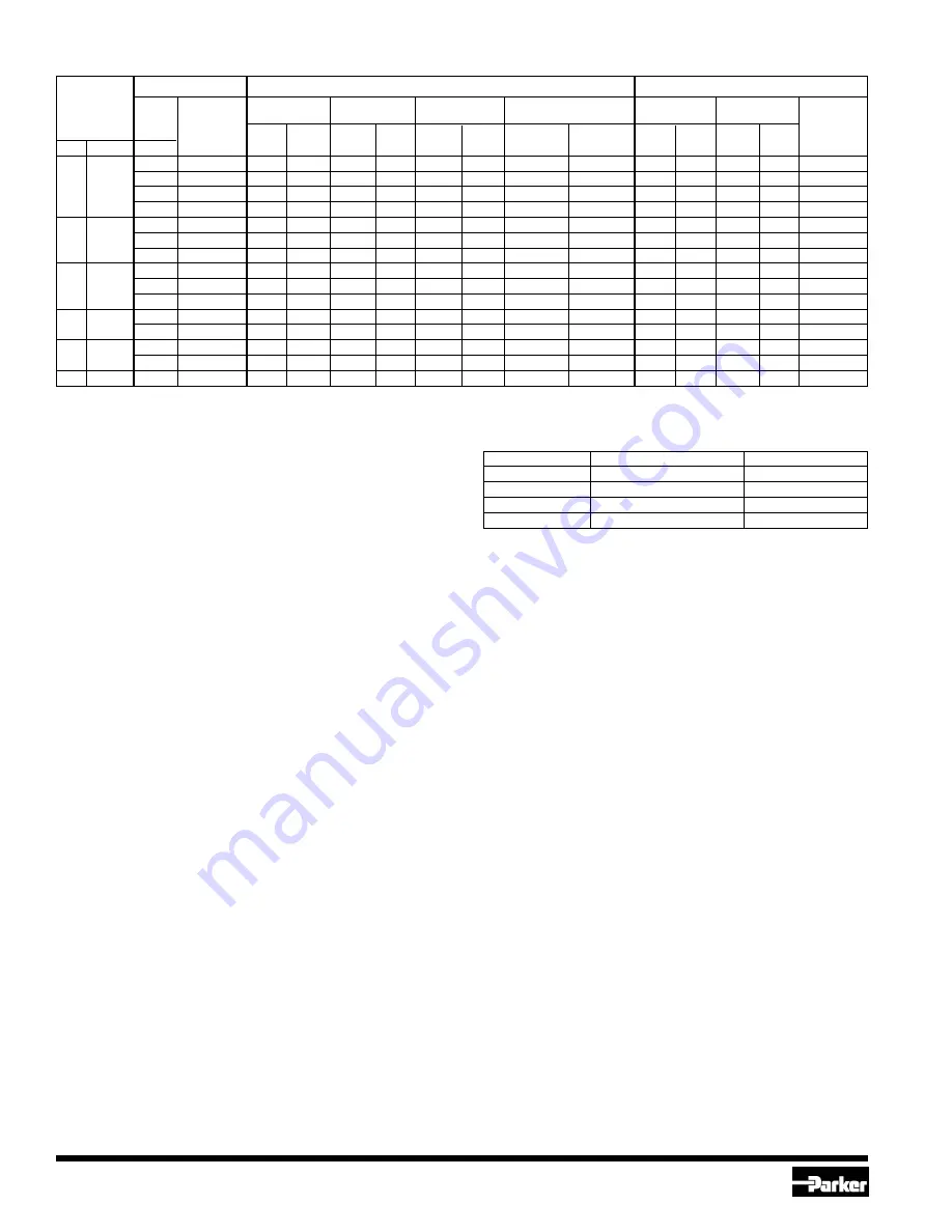
VALVE
➀
FPT FLANGES
WELDING FLANGES
➃
ODS FLANGES
SIZE
Nom
Nominal
Sock Weld
Weld Neck
Tubing
Fitting
Pipe
Pipe Size
Socket I.D.
Neck O.D.
Part No.
O.D.
I.D.
Part
Size
Part
➁
Socket
Weld
➂
No.
mm
Inches
Inches
No.
Inches NW No. Inches
mm
Inches
mm
Weld
Neck
Inches
mm
Inches
mm
1/2
00-1179-00
1/2
15
0.860
21.84
—
—
00-1180-00
N.A.
7/8
22.22
0.877
22.27
30-0108-13
20
3/4
3/4
00-1181-00
3/4
20
1.070
27.81
1.050
26.67
00-1114-00
00-1182-00
1-1/8
28.57
1.130
28.70
30-0108-10
and
and
1
00-1031-00
1
25
1.365
34.67
1.315
33.40
00-1033-00
00-1098-00
1-3/8
34.92
1.380
35.05
30-0108-11
25
1
1-1/4
00-1117-00
1-1/4
32
1.705
43.31
1.660
42.16
00-1118-00
00-1155-00
1-5/8
41.27
1.631
41.43
30-0108-12
1-1/4
00-1094-00
1-1/4
32
1.705
43.31
1.660
42.16
00-1035-00
00-1100-00
1-3/8
34.92
1.380
35.05
30-0109-10
32
1-1/4
1-1/2
00-1120-00
1-1/2
40
1.930
49.02
1.900
48.26
00-1121-00
00-1161-00
1-5/8
41.27
1.631
41.43
30-0109-11
2-1/8
53.97
2.131
54.13
30-0109-12
40
1-5/8
1-1/2
00-1038-00
1-1/2
40
1.930
49.02
1.900
48.26
00-1040-00
00-1103-00
1-5/8
41.27
1.631
41.43
30-0110-10
and
and
2
00-1042-00
2
50
2.445
62.10
2.375
60.33
00-1044-00
00-1074-00
2-1/8
53.97
2.131
54.13
30-0110-11
50
2
2-5/8
66.67
2.631
66.83
30-0110-12
65
2-1/2
2-1/2
00-1047-00
2-1/2
65
2.945
—
2.875
73.03
00-1070-00
00-1049-00
2-5/8
66.67
2.631
66.83
30-0111-10
3-1/8
79.37
3.131
79.53
30-0111-11
75
3
3
00-1053-00
3
80
3.575
90.81
3.500
88.90
00-1071-00
00-1055-00
3-1/8
79.37
3.131
79.53
30-0112-10
3-5/8
92.07
3.631
92.23
30-0112-11
100
4
4
00-1057-00
4
100
4.575
116.20
4.500
114.30 00-1104-00
00-1059-00
4-1/8
104.77
4.132
104.95 30-0113-10
➀
FPT: Internal NPT (USA Standard Taper Pipe Thread).
➁
NW: Metric equivalent nominal size for steel tubing.
➂
Metric copper tubing used for refrigeration.
➃
ODS connections to fit copper tubing of given outside
d
iameter. (Not for use with ammonia)
Definitions:
ODS - Outside Diameter Sweat
I.D. - Inside Diameter
O.D. - Outside Diameter
N.A. - Not Available
Flange Bolt Torque Requirements
Bolt Diameter
Valve Port Size
Torque
11 mm (7/16")
13mm (1/2 ")
3.9 mkg (28 ft lb)
16m m (5/8")
20-50mm (3/4 "- 2")
11.8 mkg (85 ft lb)
19m m (3/4")
65-75mm (2-1/2 "- 3")
14.5 mkg (105 ft lb)
22mm (7/8")
100mm (4")
22.1 mkg (150 ft lb)
FLANGE TABLE
SAFE OPERATION
(See Bulletin RSB for further information.)
The personnel doing any work on a refrigeration system must be
qualified and completely familiar with the system, or all other
precautions will be meaningless.
Where cold liquid lines are used, it is important that certain
precautions are taken to avoid damage due to liquid expansion.
Temperature increase in a section full of solid liquid can cause high
pressures due to the expanding liquid and possibly rupture a gasket,
pipe or valve. All hand valves in such locations should be marked,
warning against accidental closing, and must not be closed until the
liquid is removed. Check valves must never be installed upstream of
solenoid valves or regulators with electric shut-off, nor should hand
valves upstream of solenoid valves or downstream of check valves
be closed until the liquid has been removed. It is advisable to install
relief devices in any section where liquid expansion could take place.
For the protection of personnel and products, all refrigerant should
be removed from the section to be worked on before a valve, strainer
or other device is opened. Special care should be taken when
pumping out a strainer, liquid may be trapped in the strainer and
considerable time may be required to remove it.
Strainer inspection is of utmost importance, especially the first few
hours, days or weeks after the start-up. The strainers should be
opened and any dirt removed. Strainer inspection and cleaning should
be continued until dirt accumulation ceases. Later, any time a valve
is opened for service or maintenance, its companion strainer should
also be inspected and cleaned.
WARRANTY
All Refrigerating Specialties products are warranted against defects in
workmanship and materials for a period of one year from date of shipment
from originating factory. This warranty is in force only when products are
properly installed, maintained, and operated in use and service as
specifically stated in Refrigerating Specialties Catalogs or Bulletins for
normal refrigeration applications, unless otherwise approved in writing by
Refrigerating Specialties Division. Defective products, or parts thereof
returned to the factory with transportation charges prepaid and found to
be defective by factory inspection will be replaced or repaired at
Refrigerating Specialties option, free of charge, F.O.B. factory. Warranty
does not cover products which have been altered or repaired in the field;
damaged in transit, accidents, misuse, or abuse. Products disabled by
dirt or other foreign substances will not be considered defective.
The express warranty above constitutes the only warranty of Refrigerating
Specialties products, and is in lieu of all other warranties, expressed or
implied, written or oral, including any warranty of merchantability or
warranty of fitness for a particular purpose and in no event is
Refrigerating Specialties responsible for any consequential damages
of any nature whatsoever. No employee, agent, dealer or other person
is authorized to give any warranties on behalf of Refrigerating Specialties
nor to assume for Refrigerating Specialties any other liability in connection
with any of its products.
FACTORY REPAIR AND REBUILDING
For the convenience of our customers, we have a standard factory repair
and re-building service. Repairable returned Regulators are disassembled,
cleaned, sandblasted, worn parts replaced, reassembled, and re-painted.
For quickest service, it is advisable that this be done during the off peak
season.


