


Refrigerating Specialties Division
11
MAINTENANCE AND SERVICE
GENERALPROCEDURE:
Dirt in the system is the greatest single cause of regulator malfunction.
All screens or filters must be cleaned or replaced when they become
dirty. At start up it is especially important that these items are cleaned
or changed frequently. When the RSF close-coupled companion
strainers are used, maintain according to instructions in Bulletin 00-10D.
Moisture in halocarbon systems in particular can cause corrosion or
form ice, causing the piston to freeze in position. Filter-driers should be
used and maintained for halocarbon systems.
Before deciding to disassemble a regulator for servicing, the following
investigations should be made:
Check the manual opening stem; it should be turned in for automatic
operation.
Check the regulator setting to make sure it is properly adjusted.
Turn adjusting screw slowly to see if regulator responds. Check
regulator pressure range; if wrong, range spring must be replaced.
Check other system components for proper operation. Make sure
that the regulator receives the proper electrical signal where modular
pilot solenoids or motors are used.
Check hand valves in the system to make sure they are open or
closed as required and the system is receiving liquid or gas as the
case may be. Check modular pilot solenoid or motor voltage and
frequency (Hz). Make sure they are same as the power supply.
Before disassembly of regulator, make certain that all refrigerant
has been removed (pumped out) from the regulator and its
companion strainer where one is used. Read Safety Bulletin RSB.
SOLENOID COILS AND COIL HOUSING
The solenoid coils and coil housing, identified and described on pages
6 and 7 for the Type S6A Solenoid Pilot, are an improved design which
provide a higher MOPD and a cooler coil resulting in longer life. The
new coil and its heavily plated, rust resisting housing are interchangeable
with the obsolete coil and cast iron housing as follows: The new coil,
which has its 30-0041-XX Series Part Number stamped on the side,
can be used in both the old and new coil housing; the old coil which has
its 30-0030-XX Series Part Number stamped on one end, can be used
in the old, cast iron housing only. There is no bottom marking on the
new coil; either end may be positioned up. The color coding of lead
wires for various voltages and frequencies has not been changed. The
fuses used with the old coils are suitable for the new coils; the new coil
power consumption is 30 Watts instead of 37.
The S6A pilot solenoid valve is also available with a coil using a quick
electrical connector or plug, permitting easy wiring connection with an
exposed rubber covered cable instead of a rigid or flexible conduit and
enclosed wiring. This type of coil cannot be used with the old, cast iron
housing.
The new coils and new housing described above for the S6A valve are
also used with Solenoid valve Types S4, S5, S6N, S7, S8 and S9.
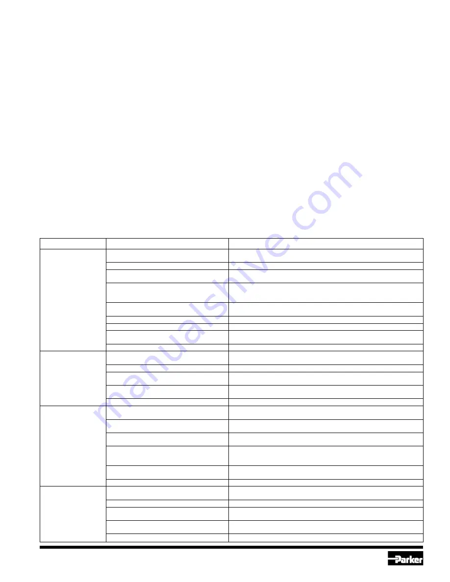
SYMPTOM
PROBABLE REASON
CORRECTION
Regulator does not
Diaphragm or seat dirty, damaged
Clean or replace. Clean strainer,
shut off flow.
or frozen.
Diaphragm follower stuck or damaged.
Clean or replace. Install follower carefully.
Piston jammed with excess dirt.
Remove and polish piston and bore with crocus cloth.
Clean valve and strainer.
Throttling plug leaking due to excess
Clean or replace. If used on liquid, check for erosion due to excessive
dirt or damage.
flash gas. Reduce flash gas by subcooling or by reducing pressure drop
across valve by providing restriction at valve outlet.
A4AO Pilot Plug sticking.
Check for dirt, corrosion or damage. Clean or replace.
Check mating bore and seat in adapter.
A4AO Diaphragm ruptured or badly deformed.
Replace. If Range “D” make sure has 2 diaphragms.
A4AB Modular Solenoid Pilot seat leaking.
Check seat and needle. Replace as needed.
Diaphragm and seat eroded due to flash gas.
Replace. Reduce flash gas by subcooling or by reducing pressure drop
across regulator by providing restriction at valve outlet.
Modular Solenoid Pilot not closing.
Check power at leads, make sure coil is de-energized.
Regulator does not
A4A (inlet) Pressure Regulator Diaphragm
Replace. If Range D make sure has 2 diaphragms.
open.
ruptured or badly deformed,
Diaphragm follower stuck, damaged or frozen.
Clean or replace. Install follower carefully.
A4AO Pilot Plug sticking.
Check for dirt, corrosion or damage. Clean or replace.
Check mating bore and seat in the adapter.
A4AS Modular Solenoid Pilot not opening.
Pressure drop across valve too high: over 21 bar (300 psig).
Lower pressure drop. Improper power supply. Correct. Replace solenoid coil.
Piston worn, too much clearance.
Replace piston. Check for reason. If used on liquid, check for flash gas.
Regulator operation
Diaphragm or seat dirty or damaged.
Clean or replace.
erratic.
Clean strainer.
A4AO Pilot Plug sticking.
Check for dirt, corrosion or damage. Clean or replace.
Check mating bore and seat in the adapter.
Diaphragm follower has dirt on the outside
Clean or replace.
diameter or outside diameter is damaged.
A4AP or A4A3P has moisture in the
Clean or replace follower. Use filter-drier in the pneumatic line. May be
pneumatic line causing the diaphragm
necessary to use remote pilot in above freezing ambient.
follower to freeze in position.
Other system components, line controllers,
Adjust, repair or replace.
thermostats, etc., erratic.
Regulator too far oversized.
Check load. Replace with smaller regulator.
Pressure drop across
Inlet or outlet restricted.
Check for restriction. Clean strainer.
regulator too high.
Regulator too small.
Replace with proper size regulator.
Large amount of flash gas in liquid line.
Reduce flash gas by subcooling. Reduce line restriction by increasing line size,
particularly at the regulator outlet. Replace with larger regulator.
High pressure drop causes high rate of
Increase pipe size at the outlet of the regulator.
expansion of gas at regulator outlet.
Regulator does not open all the way.
Check piston for wear. Replace, if needed.
SERVICE POINTERS (Check General Procedure)


