19
8903/IM 8903/IP Ethernet Communications Interfaces
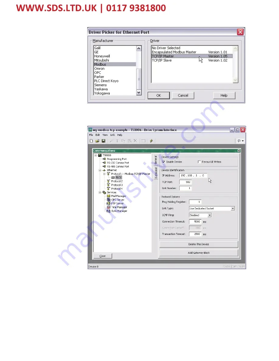
16.
Set the Slave IP address to match the one configured in the 890.
Страница 1: ...m Parker SSD Drives a division of Parker Hannifin Ltd Although every effort has been taken to ensure the accuracy of this document it may be necessary without notice to make amendments or correct omis...
Страница 2: ...benefit from the equipment Application Area The equipment described is intended for industrial motor speed control Personnel Installation operation and maintenance of the equipment should be carried...
Страница 3: ...In particular Stored energy might not discharge to safe levels as quickly as suggested and can still be present even though the drive appears to be switched off The motor s direction of rotation might...
Страница 4: ...figuring the Ethernet TechCard using DSE 890 9 Step 1 1 Inserting an Ethernet Function Block 9 Step 1 2 Attaching Fieldbus Connectors 10 Step 1 3 Configuring the Fieldbus Connectors 11 DSE Data Types...
Страница 5: ...dalone Drive using 890 firmware version 3 2 onwards Galvanically isolated bus electronics 10 100Mbit operation LEDs to indicate network and module status Supports Modbus TCP protocol 8903 IM only Supp...
Страница 6: ...Board 1 Remove the blank covers each secured by a single screw that fit over the TechCard holes 2 Loosen the top and bottom screws in the handles of the Control Board 2 3 Pull gently on the handles a...
Страница 7: ...protrude through into the connector on the other side of the TechCard 2 Press the assembly into the TOP connector adjacent to terminals X10 X11 and X12 on the Control Board Ensure that the front pane...
Страница 8: ...boards into the slots Push until the back edge of the Control Board pcb locates with the connectors in the drive 2 Tighten in position using the top and bottom screws in the blue handles of the Contro...
Страница 9: ...ugs into the PLC for example and into the socket on the Ethernet techbox Note When connecting to one drive direct from PC PLC you must use a crossover cable RJ45 Standard Pin Details Pin Signal 1 TD 2...
Страница 10: ...Address set GREEN ON Normal operation GREEN FLASHING Waiting for connections RED ON Duplicate IP Address Figure 7 Modbus TCP NS LED Ethernet IP Colour LED Indication Description OFF OFF No power or n...
Страница 11: ...IP Address RED FLASHING Minor fault Figure 9 Modbus TCP MS LED Ethernet IP Colour LED Indication Description OFF OFF No power GREEN ON Controlled by a Scanner in Run state GREEN FLASHING Not configur...
Страница 12: ...ED XXX XXX XXX XXX The IP Address of the computer running Drive System Explorer DSE is displayed if connected to the 890 via Ethernet If DSE is not connected then NOT CONNECTED is displayed Note this...
Страница 13: ...rd using DSE 890 Step 1 1 Inserting an Ethernet Function Block Display your configuration page Click on the Block menu at the top of the screen 1 Move the cursor down to select 890 Comms and select Et...
Страница 14: ...tput FB Value Output FB Val to Int Output Input connector the data is sent from PLC 890 Output connector the data is sent from 890 PLC The fieldbus connectors must be added before they will appear in...
Страница 15: ...elected To configure the input and output connectors you have placed in the configuration 1 Expand the Inputs and Outputs trees to reveal the registers By default the trees each have one register To a...
Страница 16: ...e master Low Word First is sometimes referred to as Modicon Mode and is used when the least significant 16 bits are sent in a lower register number than the most significant 16 bits i e Little endian...
Страница 17: ...ger 2 147 438 648 to 2 147 483 647 4 UINT16 16 bit unsigned integer 0 to 65 535 2 USINT32 32 bit unsigned integer 0 to 4 294 967 295 4 FLOAT 32 bit IEEE 754 floating point value 1 19209290e 38 to 3 40...
Страница 18: ...2 Place an MSTR block in the ladder logic MSTR blocks move data from the PLC data table to the drive or from the drive to the PLC data table Two MSTR blocks are necessary for a Read and Write operati...
Страница 19: ...selected parameter set 6 The fourth register defines the Read and Write locations of the data in the PLC address 40103 or address 40203 For a Read function this value is set to 1 and for a Write func...
Страница 20: ...processor and 1756 A7 B rack Remain Offline until you are ready to download the program 10 Using the I O Configuration insert the Ethernet interface that will be installed Right click on the I O Conf...
Страница 21: ...s format will be DATA Int if 16 bit signed integer or Data REAL if 32 bit floating point The Input Assembly Instance is 100 and the Output Assembly Instance is 150 Refer to Figure 20 13 Click on Next...
Страница 22: ...an be downloaded to the PLC For testing purposes it is not necessary to program Ladder Logic in the PLC The data can be accessed and monitored via Controller Tags Refer to Figure 21 TS8000 Operator St...
Страница 23: ...19 8903 IM 8903 IP Ethernet Communications Interfaces 16 Set the Slave IP address to match the one configured in the 890...
Страница 24: ...rnet Communications Interfaces 17 The name of the Slave can be changed and additional Slaves added 18 Create Tags for reading and writing variables Create either an Integer or a Real variable and map...
Страница 25: ...mber is 00002 if the first Input variable is a 16 bit data type or 00003 if it is a 32 bit data type To read the first Output variable declared in DSE the Register number is set to 00257 To read the s...
Страница 26: ...ng This is an alternative to the USB connection with the advantage of speed and remote connection Note it is not possible to Install Firmware over Ethernet this must always be done over USB Click on t...
Страница 27: ...valid offset n 2005 Invalid length offset n 2006 Invalid SDDA Slave Device Data Area n 2007 Invalid SDNA Slave Device Network Address n 2008 Invalid SDNR Slave Device Network Routing n 2009 Invalid ro...
Страница 28: ...e n 6m04 Exception response received n 6m05 Route node data paths busy n 6m06 Slave device down n 6m07 Bad destination address n 6m08 Invalid node type in routing n 6m10 Slave rejected the Modbus comm...
Страница 29: ...the module still has limited communications but has a Major Fault or is currently being Flash Updated Refer to the Module Info tab to determine the exact cause 16 0013 Module Configuration Invalid dat...
Страница 30: ...e one requested Either increase the requested RPI or decrease the RPI the owner controller is using See the Connection tab for valid RPI values 16 0113 Connection Request Error Module connection limit...
Страница 31: ...t up a connection with the module and cannot resources required are unavailable Module Faults 16 0200 16 02ff Code String Explanation and Possible Causes Solutions 16 0203 Connection timed out The con...
Страница 32: ...on with the module and has received an error 16 0312 Connection Request Error Invalid link address The controller is attempting to set up a connection with the module and has received an error an inva...
Страница 33: ...C to UINT32 False True 0 1 From LOGIC to FLOAT False True 0 0 1 0 INTEGER Type Connector Data from PLC Data to DSE From SINT16 to INTEGER 32 768 to 32 767 32 768 to 32 767 From SINT32 to INTEGER 2 147...
Страница 34: ...2 767 0 limits apply From FLOAT to VALUE 32 bit IEEE floating point 32 768 0 to 32 767 9999 limits apply Data from DSE Data to PLC From VALUE to SINT16 32 768 0 to 32 767 9999 32 768 to 32 767 limits...
Страница 35: ...CHK D 1 Initial Issue HA500522U001 New Terms and Conditions document number 17852 20358 03 04 08 CM KJ 2 Small corrections to pages 10 21 17852 21 04 08 CM KJ FIRST USED ON MODIFICATION RECORD 8903 I...