


At the other end of the bed, locate
the top and bottom side rails to the
assembled side rail slides, inserting
the protruding steel fingers into the
corresponding holes in the ends of
the rails. Carefully leave the other
ends of the rails resting on the floor.
Insert the steel “fingers” of the side
rail slide assembly into the holes in
the side rail slide as shown in the
diagram. Then insert the top of the
side rail slide into the aluminium
channel (painted end upwards);
inserting the nylon spacer into the channel before sliding the complete
assembly up into the channel using the upper rail until fully home and
the release button latch engages with an audible click.
Replace the retaining block in the bottom of the aluminium channel.
Screw in the thumbscrew ensuring the threaded end of the screw full
locates in the hole in the back of the aluminium channel, with the
threaded end of the screw located in the hole in the channel as
previously described.
Warning. The correct location of the threaded end of the screw into the
hole in the aluminium channel is essential to prevent the side rail slide
assembly from dropping out of the bottom of the channel when in use.
Lower the head end of the mattress support onto the tubular cross
member at the head end of the lifter chassis, ensuring the location
cups are completely seated on the ends of the tubular cross member.
Screw in completely and tighten the thumb screws. Do not over
tighten.
Using a flat blade screwdriver gently pry open the cable-retaining
strap on the main control unit located at the head end of the lifter
chassis. Locate the multi-pin plugs on the various power cables and
fully insert them in their respective sockets in the main control unit.
The plugs and sockets are labeled and should correspond like for like
when inserted. When all plufs are inserted snap the retaining strap
into position to prevent the plugs being accidentally pulled out as the
bed is used.
Warning. Ensure that all spiral wound cables are clear of the scissor
mechanism and that there is sufficient slack to enable a smooth
operation. Periodically check all cables for any damage or chafing.
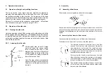
4.3 Assembly of the wooden head/foot boards and side rails
Note: Please select upper side rail or bottom side rail before
assembly. (see diagram)
Orientate the head and foot boards (they are
interchangeable) with the aluminium channels facing
inwards towards the bed as per diagram. Offer up to the
threaded lugs on the bed frame ends and secure in
position using 4 off M8x25 mm dome headed screws. Do
not over tighten. At one end of the bed, loosen the
retaining thumbscrew in the retaining block located at the
bottom of the aluminium channels on both side of the
head/foot board until the retaining block slides out of the
aluminium channel. Do not remove the screw completely
from the block. Remove the pre assembled side rail slide
assembly, noting the way that the slide connector is
attached to the fingers and where the loose nylon spacer
is located. (see diagram)


