


Dowel pin
5. Operation Instructions
5.1 Operation of height and profiling functions
The head section, knee break and bed height are adjusted by
pressing the appropriate button on the hand controller. The buttons
are lavelled according to their function. On the reverse of the hand
controller there is a clip that allows the hand controlelr to be stored on
either of the side rails or on the head/foot boards as appropriate.
Warning. Do not exceed the maximum usage period - all functions
have a maximum usage of 6 minutes per gour (10%).
5.2 Operation of the side rails
5.2.1 Raising the side rails
Hold the upper side rail and lift by moving up the slide channel until the
latch engages with an audible click. (It is advisable for safety reasons
to raise the head end first). Release the rail and it will stay in position,
as the rails are joined together the lower rail will also have been lifted
and will stay in position.
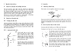
5.2.2 Lowering the side rails
Lift the upper side rail until it stops
and hold, push the spring loaded
latch release button fully in (see
diagram) and then lower the side rail
until the bottom rail rests onf the stop.
(It is advisable for safety reasons to
lower the foot end first).
Note: The side rails are automatically
spaced at all times so that the carer’s
fingers are not trapped as railers are
lowered.
4. Assembly
4.1 Assembly of bed frame
Slide the side sections together as indicated in the diagram.
Ensure both sections fit fully together until the outer tubes touch each other
and fir the securing dowels and pins on both sides of the bed frame before
tightening the thumbscrews on the under side of the bed frame. Do not over
tighten.
4.2 Assembly of bed frame to lifted chassis
Once assembled the bed frame can be fitted to the lifted chassis.
Firstly identify the “head” and “foot” ends of the lifter chassis.
The lift motor is located at the “foot” end of the lifter
chassis. There is also a roller either end of the tubular
cross member on the foot end. The “head” end has a
similar tubular cross member with rollers that is shorted
in length (note: this will only allow the unit be be
assembled the correct way around)
First unscrew the thumb screws located on the both
sides of the head section of the bed frame in the location
cups (see diagram). Unscrew leaving nothing protruding
through on the inside. Do not remove completely.
Once located slide the parallel guide-ways on either side
of the foot end of the bed frame onto the rollers at the
foot end of the lifter
chassis.


