background image

 8 

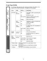
Front Panel LEDs

The following table describes the meaning and states of the LEDs on the
Hotwire 8775 or 8785 TDM SDSL Termination Unit’s faceplate.

Type

LED

LED is . . .*

Indicating . . .

SYSTEM

OK
(Green)

On

Off

Slow Cycling

Pulsing

Unit failure; system processing has
stopped.

No power to card.

Unit is in minimum mode and a
download is required.

Normal operation.

Alrm
(Amber)

On

Off

Unit failure, or Power-On Self-Test
(POST) has failed.

No alarms.

Test
(Amber)

On

Slow cycling

Off

Loopback test or 511 test pattern in
progress.

POST in progress.

No tests.

SYNC
PORT

1, 2, 3, 4
(Green)

On

Off

The port is operational.

No signal on the port, or DTR or
RTS is off.

DSL
PORT
LINK-UP

1, 2, 3, 4
(Green)

On

Slow cycling

Fast cycling

Off

DSL link is up.

DSL training in progress.

OOF condition.

DSL link is down.

* Slow Cycling:

LED turns off and on in equal duration once 
per second.

Fast Cycling:

LED turns off and on in equal duration 5 times 
per second.

Pulsing:

LED turns off momentarily once per second.

4

TDM

SDSL

8775

SY

S

TE

M

OK

Alrm

Test

1

2

3

1

2

3

SY

N

C

 P

O

RT

D

S

L P

O

R

T

   LIN

K

-U

P

4

00-15834-03

Содержание Hotwire 8785

Страница 1: ...ation Units Models 8775 and 8785 User s Guide For information about the DSLAM or MCC select from the following documents 8000 A2 GB22 Hotwire Management Communications Controller MCC Card IP Conservat...

Страница 2: ...ling the unit in the DSLAM H Connecting to the Data Terminal Equipment DTE H Connecting to a Main Distribution Frame MDF H Providing initial unit identity information or changing existing identity inf...

Страница 3: ...re No 8700 F1 501 H X 21 100 position plug to four DB15 like Paradyne Feature No 8700 F1 502 H RS 449 100 position plug to four DB37 like Paradyne Feature No 8700 F1 503 H EIA 530 A 100 position plug...

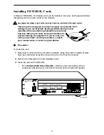
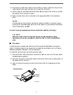
Страница 4: ...ermine in which slot the unit will be installed Verify that cards in adjacent slots have been fastened using the screws at each end of their front panels 2 Remove the filler plate from the installatio...

Страница 5: ...D S L P O R T L IN K U P 4 4 Slide the unit into the slot until the power and network connectors seat firmly in the mating connectors on the backplane CAUTION Do not force the unit into the slot This...

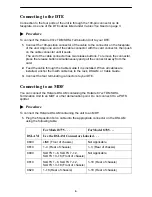
Страница 6: ...it is installed When all cables are installed anchor them with cable ties to the rack DSLAM or Cable Guide 3 Connect the four terminating connectors to your DTE Connecting to an MDF You can connect th...

Страница 7: ...CAUTION All ferrite chokes that are supplied must be installed following these instructions to ensure compliance with FCC Part 15 VCCI and CISPR22 rules Procedure A ferrite choke is included with all...

Страница 8: ...mber On Slow cycling Off Loopback test or 511 test pattern in progress POST in progress No tests SYNC PORT 1 2 3 4 Green On Off The port is operational No signal on the port or DTR or RTS is off DSL P...

Страница 9: ...Hotwire 8775 or 8785 TDM SDSL Termination Unit s various ATI screens Main Status Test System and Test Status Performance Statistics Display LEDs Identity Network Error Statistics Network Performance...

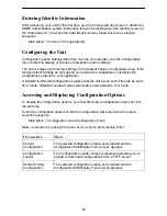
Страница 10: ...SLAM configuration requires that the unit at one end of the link be set to NTU mode DSLAM mounted Hotwire termination units default to LTU mode Accessing and Displaying Configuration Options To displa...

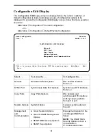
Страница 11: ...munication Ctrl a to access these functions ESC for previous menu MainMenu Exit Save Select To Access the To Configure the Network Network Interface Options DSL network interface Ports 1 4 SYNC Port S...

Страница 12: ...ompany representative Within the U S A call 1 800 870 2221 Outside the U S A call 1 727 530 2340 Document Feedback We welcome your comments and suggestions about this document Please mail them to Tech...

Отзывы: