Paradyne FrameSaver SLV 9580 T3 ATM DSU Скачать руководство пользователя страница 9

 9

9580-A2-GZ40-10

June 1999

Connecting the DTE Cables

The FrameSaver SLV 9580 DSU can be connected to two DTEs. Each may have
either a HSSI or a V.35 interface. The FrameSaver SLV 9580 DSU automatically
detects the presence of a V.35 adapter. If Port Type is set to HSSI and a V.35
adapter is installed, or if Port Type is V.35 and a V.35 adapter is not installed, an
error message is displayed on the Health and Status screen and the Port-

n

Physical Options configuration screen. The port is not usable when the Port Type
and cable do not match.

The DTE sockets require 50-position 0.5-inch straight exit connectors. Molded
connectors cannot be used. DTE cables are not supplied with the DSU.

NOTE:

If you wish to isolate the router from network activity until proper network
operation has been verified, do not connect the router to the DSU until the
network has been configured and network connectivity has been verified.
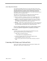
Procedure

To install a V.35 or HSSI DTE cable:

1. Press the 50-pin connector of the HSSI cable or the V.35 adapter onto the

DTE P1 or DTE P2 socket on the back of the DSU until the latches lock.

2. For a HSSI cable, proceed with Step 3. Connect the V.35 cable to the V.35

adapter, providing appropriate strain relief.

3. Fix the cable to the rail with a cable tie or other strain relief device.

4. Connect the other end of the cable to the appropriate port of your DTE.

1

2

3

5

4

DTE P1

DTE

98-16027

Do not substitute a SCSI-2 cable for a HSSI cable. Although apparently
similar, a SCSI-2 cable may not accommodate high speeds without errors.

Содержание FrameSaver SLV 9580 T3 ATM DSU

Страница 1: ...t the DSU to an Ethernet interface Connect the DSU to a terminal or PC directly or through a modem Enter a device profile Set up system Login IDs and access levels Configure the system Configure manag...

Страница 2: ...e mounted in a standard 19 inch or 23 inch cabinet or open rails and either flush with the mounting rails or approximately 4 inches forward of the rails The different configurations are accommodated b...

Страница 3: ...line up precisely with holes in the rail 2 Mark the holes in the rail where the two machine screws will go Then mark the opposite rail in the same positions 3 If the rack has threaded holes go to Step...

Страница 4: ...kets to the DSU with four 8 flathead screws Fra meSaverTM SLV 95 80 AI S XM T RC V LC V OO F LO S YE L PO RT 1 TD RD DS R DT R PO RT 2 NE TW OR K TD RD DS R DT R SY ST EM OK AL M TS T PW R FA N 98 160...

Страница 5: ...ver SLV 9580 DSU into position in the rack putting the screws through the keyed holes of the bracket Lower the DSU onto the screws 98 16024 8 Put a machine screw through the top hole of each bracket a...

Страница 6: ...connector of the power cable into the power receptacle on the back of the FrameSaver SLV 9580 DSU Fix the cable to the rail with a cable tie or other strain relief device 3 Connect the other end of th...

Страница 7: ...essage What It Indicates What To Do Bypassed Self test was disabled when the unit was powered up or reset No action needed CPU Fail The CPU failed internal testing 1 Reset the unit and try again 2 Cal...

Страница 8: ...the back of the FrameSaver SLV 9580 DSU Turn the cable connector clockwise to lock it 3 Fix the cables to the rail with a cable tie or other strain relief device 4 Connect the receive and transmit cab...

Страница 9: ...with the DSU NOTE If you wish to isolate the router from network activity until proper network operation has been verified do not connect the router to the DSU until the network has been configured a...

Страница 10: ...t supplied with the FrameSaver SLV 9580 DSU Procedure To connect the FrameSaver SLV 9580 DSU to an Ethernet hub or NIC 1 Select the correct cable To connect the LAN port to a hub use a standard 10Base...

Страница 11: ...connector of the cable onto the TERMINAL PORT socket on the back of the FrameSaver SLV 9580 DSU If the cable will be permanently attached fasten the connector and fix the cable to the rail with a cab...

Страница 12: ...Performance Monitoring VCC Loopback RTT Estimation Abort All Tests 98 16034a The PVC Connection Status screen allows jumps to other screens by use of virtual function keys Possible jumps are shown by...

Страница 13: ...s PVC Connection Entry Service Level Verification Entry to all of the FrameSaver SLV 9580 DSU s tasks begins at the Main Menu screen which has these menus or branches Select To Status View system stat...

Страница 14: ...I Supporting ILMI Date Time Procedure To set the Device Profile 1 Follow this menu selection sequence Main Menu Control Device Profile main control device_name PARADYNE 9580 Device Name Node A 05 13 2...

Страница 15: ...o configuration should not be run until you have used the Configure branch to set up any specific management PVCs required for your network Accessing and Displaying Configuration Options To display th...

Страница 16: ...PVC Connections Test User Interfaces Management and Communication Ctrl a to access these functions ESC for previous menu MainMenu Exit Save 3 Select the options you would like to configure Select To c...

Страница 17: ...management a corresponding DLCI for Port 1 and a management DLCI are created and connected for every VPI VCI discovered H 2MPorts An IWF DLCI containing three EDLCIs one for each port and one for mana...

Страница 18: ...2 Network PVC Tests Start and stop a PVC test in the direction of the network IP Ping Display the menu for running the PING function LED Test Perform a lamp test VCC Performance Monitoring Select Virt...

Отзывы: