


13
Cabling
The following cables are used with this product:
Model 8995 or Model 8997 using 120 Ohm outputs:
Feature Number
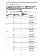
8026-F1-001, which terminates in eight 8-pin modular jacks. See
Table 1, Feature
Number 8026-F1-001 Pin Assignments, on page 18
.
Model 8997 using 75 Ohm outputs:
Feature Number 8027-F1-001, which
terminates in 16 BNC jacks. See
Table 2, Feature Number 8027-F1-001 Pin
Assignments, on page 19
.
Attach the cable to the 50-pin Telco jack that is associated with the slot the T1 or E1 line
card resides in.
Fastening the Cable with Cable Ties
Procedure
To fasten the Telco connector to the chassis using the provided cable ties:
1.
Replace the longer captive screw on the cable connector with the #4-40 Phillips
pan-head screw shipped in a plastic bag with the BLC.
2.
Locate the connector on the back of the chassis that corresponds with the slot
where you installed the T1 or E1 card. Connectors are labeled 2 and 3 on the 8620
BLC, and 1–18 on the 8820 BLC.
3.
Plug the Telco 50-pin cable into the appropriate connector.
4.
Thread the provided cable tie through the anchor mount on the end of the connector
where the cable will lie. Tighten the cable tie around the connector and cut off any
excess.
01-16900
Anchor
Mount
Telco 50-Pin
Connector
Cable
Tie
Replaced with
Supplied #4-40
Phillips Pan-head
Screw
Содержание 8995
Страница 23: ...23...
Страница 24: ...24 8990 A2 GN10 20 8990 A2 GN10 20...