© 2001 PANORAMAdtv ALL rights reserved
18
MON3-2A User Manual P/N 821521 Rev-B.5
Tally Control Connector Wiring
Section 3: Technical Information
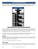
A front panel dual color (red and green) tally LED is associated with each LCD monitor. Interface is provided to
the LEDs via the Tally Control Connector. Tri-color (red, green, and yellow) tally indications are possible by
activating the red and green LED sections simultaneously. For connection details, see Figure-3a below .
Figure 3-b, on the facing page, shows sample tally connection configurations. You can operate the Tally LEDs by
numerous methods. The two tutorial examples showing isolated and non-isolated activation are illustrated to show
basic operation. Although switches are employed in these examples, the LEDs interface with TTL levels. You can
design illumination circuits as shown, by using TTL buffers, or by using transistors as switches.
The Tally indicators are capable of displaying three colors. Illuminating the red or green LEDs separately will result
in that tally color. Illuminate the red and green LEDs simultaneously to achieve a yellow tally.
Isolated
Operating the Tally LEDs in an isolated configuration requires an external (customer provided) power supply and
tally system. If your facility currently has a tally system with companion power source, use this method to integrate
the MON3-2A tallies with your existing tally matrix.
NOTE:
Ensure the LED power supply pr5 to +12VDC.
Non-Isolated
Operating the Tally LEDs in the non-isolated configuration uses the MON3-2A internal power supply to provide the
tally LED voltage. Connect your tally closures as shown in Figure-3b to the respective MON3-2A tally connections.
Figure-3a: MON3-2A Tally Control Connector Pin Function Table
MON3-2A Rear Panel


