


BA_PH_245-100-300_EN_06-22.docx
30
9
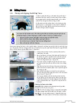
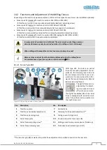
Components and Control Elements
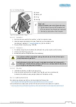
Figure 11: Components and Control Elements
Pos. Description
Pos. Description
1
Main switch position
12
Machine table
2
Milling spindle
13
Table insert rings (table slide plate optionally)
3
Control panel
with touchscreen unit
14
Table extension (left)
4
Emergency stop positions
15
Table extension (right)
7
5
Milling fence (Type 301)
16
Suction nozzles Ø 120 mm
6
Milling splinter tabs (2 x)
17
Swivel arm for control panel
7
Milling fence protective bonnet
18
Position of terminal box and machine socket
8
Adjusting screw partial fence
19
Control cabinet position
9
Vernier scale partial fence
20
Service door position
10
Fence plates (2 x)
21
Frame support
11
Handwheel for total fence (with display)
5
The main switch is located under the table top.
6
The control panel can be attached either at eye level at the top or at the bottom of the table frame.
7
The optional table extensions are available as single or double-sided versions (refer to section
2
3
1
4
20
21
13
12
14
10
9
8
7
16
11 18
17
19
6
15
5