E-mail:
Fax:
(708) 444-6993
For Instructions in Local Languages
and Technical Support:
www.panduit.com/resources/install_maintain.asp
www.panduit.com
INSTALLATION INSTRUCTIONS PN256D
6.4
Finally, push the snap-on cover forward until it clicks
into place.
6.5
Should it be necessary to remove the ferrules, the
snap-on cover can be removed by simultaneously lifting
and sliding with a small screwdriver.
6.6
To clean the jack ferrules once they are enclosed in the
jack housing, use the lint-free swabs. Gently insert a
swab through the split sleeve to wipe the jack ferrule
endface. Swabs can be moistened with alcohol.
6.7
The jack dust cover should be inserted to keep the jack
housing clean when the jack is not in use.
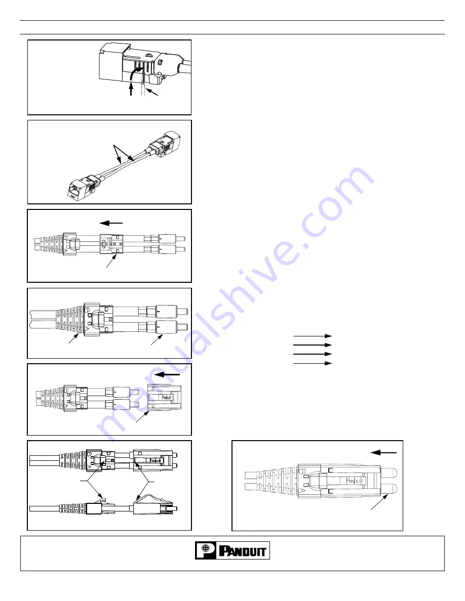
7. PLUG ASSEMBLY
7.1
Place the insert onto the cables between the boot and
terminated ferrule assemblies by sliding the cables into
the slots on the side of the insert. Be careful not to
pinch the cable. The “A” and “B” on the insert should
line up with the “A” and “B” on the boot.
7.2
Slide the insert inside the boot until the tabs on the
insert lock into the holes on the boot.
7.3
Push the ferrule assemblies into the housing. Make
sure the cables are not crossed inside the assembly.
The latch on the housing should be on the same side as
the hood on the boot.
Note: If you are using
O
PTI
-J
ACK
Keyed connectors,
verify that plug mates with intended jack
.
7.4
With the ferrule assemblies inside the housing, push
the boot/insert assembly into the housing until it snaps
in place.
7.5
Immediately after assembly, place the black dust caps
over the ferrule ends.
Page 8 of 8
With screwdriver,
push each side of
snap-on cover UP
and BACK
simultaneously
6.5
Lift UP & Slide
BACK
Screwdriver
A RUNS TO B
B RUNS TO A
B
B
A
A
For Duplex Cable, one of
these two fibers will be
lettered.
7.1
Insert
7.2
Boot
Ferrule
7.3
Housing
7.4
Boot Hood
Housing
Latch
7.5
Dust Caps
FJEPGM5CWBL
FJEPGM5CXRD
FJEPGM5CYOR
FJEPGM5CZYL
FJJGM5CWBL
FJJGM5CXRD
FJJGM5CYOR
FJJGM5CZYL


