


AT-OMNI-111 / AT-OMNI-112
14
Connection Instructions
1. Connect an Ethernet cable from the
ETHERNET
port on the encoder to a PoE-capable switch on the Local Area
Network (LAN). If using the dual-channel encoder, connect a separate Ethernet cables to
ETHERNET 1
and
ETHERNET 2
ports.
2. Connect an HDMI cable from each source to the
HDMI
ports on the encoder.
3.
RS-232 (optional)
• Connect the RS-232 controller/automation system to the
RS-232
port on the encoder.
• Connect the RS-232 device to the
RS-232
port on the decoder.
4.
IR (optional)
• IR emitter
Connect the IR emitter to the
TX
and
GND
pins of the
RS-232 2
port. The IR emitter must be placed no
more than 1” from the IR sensor on the device, in order to function properly.
• IR extender
Connect the IR extender from the
RX
and
GND
pins of the
RS-232 2
port to the associated pins on the
control system.
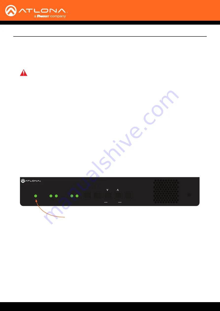
5. Once power is applied, the
PWR
indicator, on the front panel, will turn red, then amber, then green.
IMPORTANT:
If a PoE-capable switch is not available, then the 48V DC power supply (sold
separately) must be connected to the encoder.
Installation
AT-OMNI-112
ETHERNET
RS-232
DC 48V
RX TX
1
2
HDMI IN
2
1
2
1
HDMI
PWR
LINK
TM
O
MNI
S
TREAM
VOLUME
DISPLAY
INPUT
ID
1
2
1
2
PWR indicator


