AT-OMNI-111 / AT-OMNI-112
11
AT-OMNI-112
ETHERNET
RS-232
DC 48V
RX TX
1
2
HDMI IN
2
1
2
1
HDMI
PWR
LINK
TM
O
MNI
S
TREAM
VOLUME
DISPLAY
INPUT
ID
1
2
1
2
AT-OMNI-112
ETHERNET
RS-232
DC 48V
RX TX
1
2
HDMI IN
2
1
2
1
HDMI
PWR
LINK
TM
O
MNI
S
TREAM
VOLUME
DISPLAY
INPUT
ID
1
2
1
2
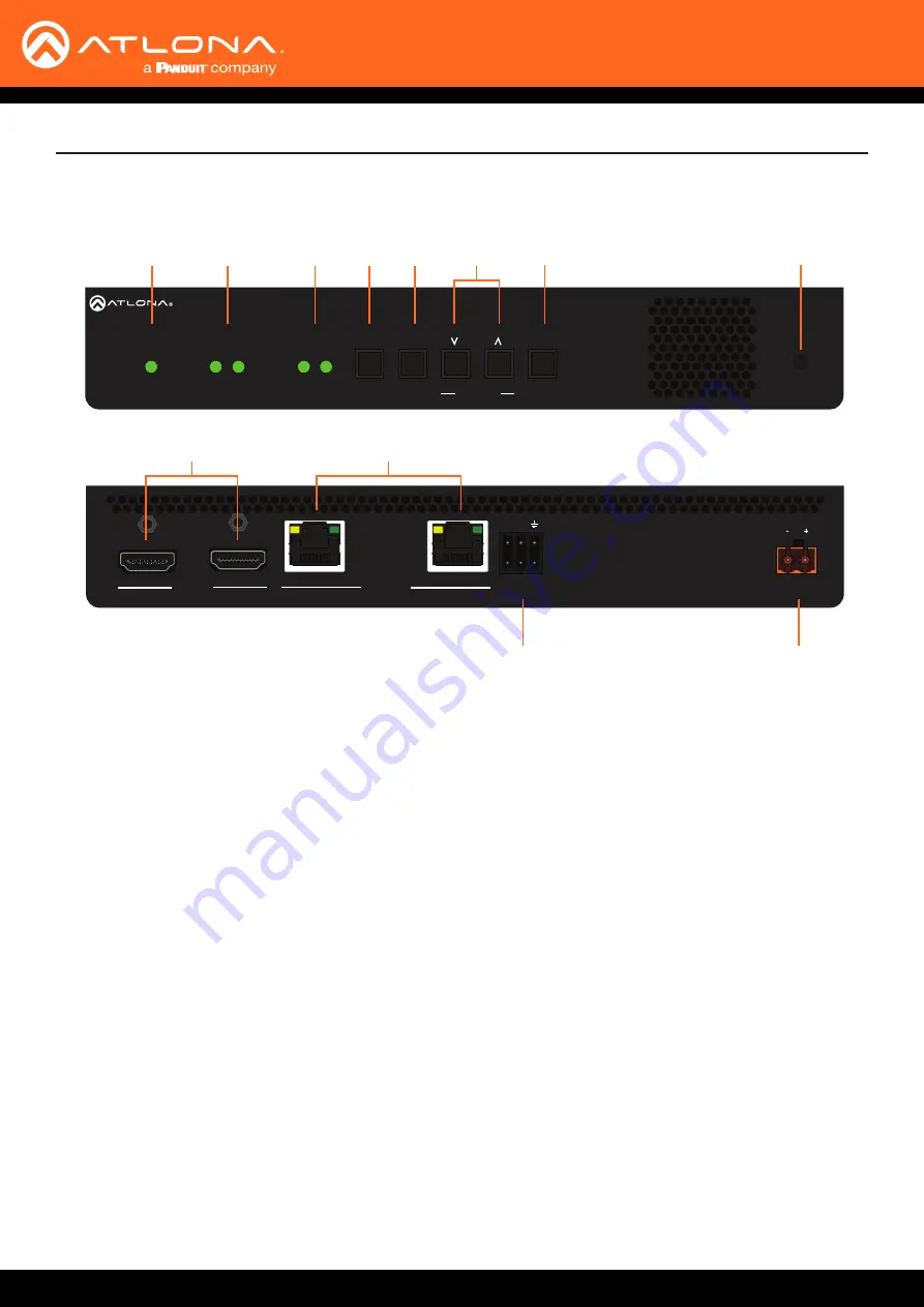
AT-OMNI-112
1 PWR
This LED indicator glows bright green when the
unit is powered.
2 HDMI 1 / HDMI 2
These LED indicators show the active input
status.
3 LINK 1 / LINK 2
These LED indicators will be green when the link
integrity between the between the encoder and
the switch is good.
4 DISPLAY
Press this button to toggle the power state of the
desired display. Refer to
for more information.
5 INPUT
Press this button to switch between HDMI 1
and HDMI 2 inputs. Refer to
for more information.
6 VOLUME
Press these buttons to adjust the output volume
of the desired display. Refer to
for more information.
7 ID
This button provides two functions:
(1) Press and release this button to send a
broadcast network notification to any devices
that may be listening (AMS).
(2) Press and hold this button for 30 seconds to
perform a factory-reset of the unit. Refer to
for more information.
8 REBOOT
Press this button, using a small, pointed object to
reboot the unit.
9 HDMI IN 1 / HDMI IN 2
Connect HDMI cables from these ports to an HD
source.
10 ETHERNET 1 / ETHERNET 2
Connect Ethernet cables from these ports to the
Local Area Network (LAN).
11 RS-232 1 / RS-232 2
Use the included Phoenix terminal block to
connect up to two RS-232 devices to this port.
12 DC 48V
Connect the optional 48V DC power supply
to this power receptacle. This power supply
is available, separately, and is required when
connecting the encoder to non-PoE compatible
switch.
Front
Rear
1
9
2
3
4
10
11
12
5
6
7
8
Panel Description


