5
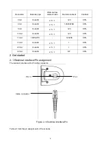
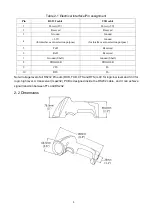
Table 2-1 Electrical interface/Pin assignment
Pin
RS232 cable
USB cable
1
Power(+5V)
Power(+5V)
2
Reseved
Reseved
3
Ground
Ground
4
+3.3V
(for interface auto selection purpose)
Ground
(for interface auto selection purpose)
5
TxD
Reserved
6
RxD
Reserved
7
Ground (Shell)
Ground (Shell)
8
TRIGGER
TRIGGER
9
CTS
D-
10
RTS
D+
Note: Voltage level of all RS232 Pin-outs (RXD, TXD, CTS and RTS) is 0V for logic low level and 3.3V for
logic high level. A transceiver (max232) PCB is designed inside the RS232 cable, and it can achieve
signal transition between TTL and RS232.
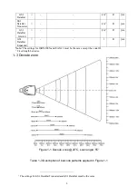
2-2 Dimensions
Содержание MD2000
Страница 1: ...MD2000 Laser Barcode Scanner User Manual Version MD2000_UM_EN_V1 1 5 ...
Страница 3: ...i ...
Страница 6: ...iv ...
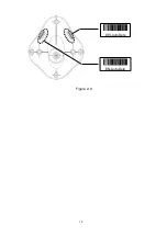
Страница 16: ...10 Figure 2 9 DIS AutoDete EN AutoDete ...
Страница 24: ...18 20 ms 03 40 ms 04 60 ms 05 Numeric key Alphabetic key 00 Numeric keypad 01 Alt keypad 02 END ...
Страница 69: ...63 END ...
Страница 79: ...73 6 Test chart A908765439 UPC A UPC E UPC E1 EAN 13 ISBN ISSN EAN 8 Code 39 Code 32 ...
Страница 84: ...78 To finish parameter setting please scan the bar code below ...


