background image

27

ENGLISH

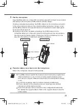
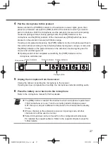
Pair the microphone to this product.

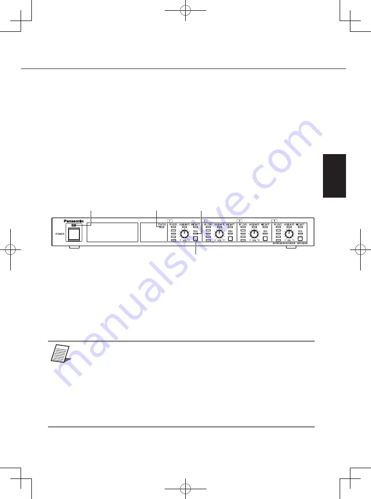
Make sure that the [POWER] indicator on the extension receiver lights green, then 

press for at least two seconds the [REG] button of the channel to which you want to 

pair a microphone. Both the microphone and the extension receiver will enter pairing 

mode and pairing will start. During pairing mode, the [PWR] indicator on the 

microphone and the [REG] indicator of the channel whose [REG] button has been 

pressed on the extension receiver will blinks orange.
If pairing is completed successfully, the [PWR] indicator on the microphone switches to 

the normal status according to the remaining battery level (green, orange, or red), and 

the [REG] indicator on the paired channel on the extension receiver lights green for 

one second and then goes off.


If pairing could not be completed successfully, the [PWR] indicator on the 

microphone will blinks red.

This product

Pairing indicator

Power indicator

Pairing button

Status indicator

Unplug the microphone from the receiver

Unplug the cables connecting the microphone to the receiver.

If pairing has been completed successfully, the microphone starts transmitting audio.

Place the battery cover back onto the microphone

Refer to the microphone manual for further details.

memo

Important


The [REG] button is invalid if the channel to which microphone is paired and 

if that microphone is in use. Turn the currently paired microphone power 

OFF, then you can pair a different microphone to the channel that is already 

in use.


When a channel on the extension receiver is in pairing mode, all other 

channels can still be used as normal.


Paired microphones can be removed from the configuration/maintenance 

PC installed the support software. Refer to the support software manual for 

further details.

PUQX1022YAV6_WX-SE200P_OI_en-fr.indb   27

2022/03/23   10:21:40

Содержание WX-SE200P

Страница 1: ...SE200P ENGLISH FRANÇAIS Before attempting to connect or operate this product please read these instructions carefully and save this manual for future use The model number is abbreviated in some descriptions in this manual PUQX1022YA PUQX1022YAV6_WX SE200P_OI_en fr indb 1 2022 03 23 10 21 36 ...

Страница 2: ...r moisture The apparatus should not be exposed to dripping or splashing and no objects filled with liquids such as vases should be placed on the apparatus The mains plug or an appliance coupler shall remain readily operable This device complies with Part 15 of the FCC Rules and Innovation Science and Economic Development Canada s licence exempt RSS s Operation is subject to the following two condi...

Страница 3: ... is likely to cause harmful interference in which case the user will be required to correct the interference at his own expense For U S A The model number and serial number of this product may be found on the surface of the unit You should note the model number and serial number of this unit in the space provided and retain this book as a permanent record of your purchase to aid identification in ...

Страница 4: ...ssories specified by the manufacturer 10 Use only with the cart stand tripod bracket or table specified by the manufacturer or sold with the apparatus When a cart is used use caution when moving the cart apparatus combination to avoid injury from tip over 11 Unplug this apparatus during lightning storms or when unused for long periods of time 12 Refer all servicing to qualified service personnel S...

Страница 5: ...X SR204P system Depending on the connected devices either channel isolated output or mix output is selectable for the audio output Limitation of liability THIS PUBLICATION IS PROVIDED AS IS WITHOUT WARRANTY OF ANY KIND EITHER EXPRESS OR IMPLIED INCLUDING BUT NOT LIMITED TO THE IMPLIED WARRANTIES OF MERCHANTABILITY FITNESS FOR ANY PARTICULAR PURPOSE OR NON INFRINGEMENT OF THE THIRD PARTY S RIGHT TH...

Страница 6: ...UNCTION FAULT SET UP OR INSTALLATION E ANY PROBLEM CONSEQUENTIAL INCONVENIENCE OR LOSS OR DAMAGE ARISING OUT OF THE SYSTEM COMBINED BY THE DEVICES OF THIRD PARTY Copyright Distributing copying disassembling reverse compiling and reverse engineering of the software provided with this product are all expressly prohibited In addition exporting any software provided with this product violating export ...

Страница 7: ...rack 18 Connections 20 Connecting the Euroblock connectors 20 Connecting audio output 21 Connecting with a receiver 22 Pairing 24 Wireless pairing 24 Wired pairing 26 How to use 28 Operating microphones 28 Confirm the signal reception level 29 Confirm the remaining battery level of the microphone 30 Confirm the paired microphones 31 Dimensions 33 Troubleshooting 34 Specifications 35 Standard acces...

Страница 8: ...it is subject to elements such as humidity thus leading to fire or electric shocks Remove the power cord and clean it with a dry cloth If the product shows any abnormality immediately stop using it If the product shows abnormalities such as smoke or an unusual smell continuing to use it may pose a fire hazard Immediately remove the power cord and contact the retailer Do not attempt to repair or wi...

Страница 9: ...m pulling on them placing heavy objects on them tying them etc Using a damaged power cord or power plug may cause electric shocks short circuits or fires Entrust the repair of the power cord and power plug to a retailer Do not insert or pull the power plug with wet hands Failing to do so may cause electric shocks Do not attempt to disassemble or remodel the product It may lead to fire or electric ...

Страница 10: ...s no power going through the extension receiver Remove the power cord from the power outlet to completely break off the flow of current to the extension receiver Power The extension receiver uses AC 120 V 60 Hz power Connect the extension receiver to an enough capacity power source Connect the power cord to the power source in one of the following ways Install the extension receiver near the elect...

Страница 11: ... malfunctions Condensation is likely to happen in the following scenarios High humidity Moving from a cold place to a hot or humid one If condensation does happen wait for one to two hours and make sure that all condensation is gone before turning ON the equipment Maintenance Perform it after having turned OFF the product It may lead to injury Clean the product with a dry soft cloth Do not use vol...

Страница 12: ... area will ensure stable operation On 5 green lines Level 5 Max On 4 green lines Level 4 On 3 green lines Level 3 On 2 green lines Level 2 On 1 green line Level 1 Min On 1 to 5 red lines Reception error All off No paired microphone or no signal from the paired microphone EAudio level indicator mute status indicator AUDIO MUTE Shows the audio level of the signal from the microphones on each channel...

Страница 13: ...n two seconds to enter pairing mode page 24 Exit pairing mode by shortly pressing the REG button once while in pairing mode A channel cannot enter pairing mode when the microphones paired to that channel are currently active Pairing confirmation Shortly press the REG button to enter pairing confirmation mode page 31 Exit pairing confirmation mode by shortly pressing the REG button once more IPairi...

Страница 14: ...IN 10 dBV 600 Ω Takes external audio input to be mixed and sent to the mix output connector MMix output connector MIX OUT 10 dBV 600 Ω Outputs audio obtained by mixing the audio from each channel with the audio input from the AUDIO IN connector NSIGNAL GND connector SIGNAL GND Gathers the SIGNAL GND from external devices to eliminate electrical potential difference OPower cord Connect the power co...

Страница 15: ...iling to do so may lead to damage to the shape and color of the product and may cause it to malfunction Also avoid exposure to water droplets and bubbles Turn the product OFF to install it Remove the power cord from the power socket before performing these operations Also turn OFF all mixers amplifiers and other devices connected to the extension receiver Failing to do so will result in a loud noi...

Страница 16: ...ower Connect the product to an enough capacity power source Power Turning the power switch to OFF will turn the product OFF but it will not interrupt the flow of current Connect the power cord through a power breaking device in one of the following ways in order to be able to easily switch it OFF Install the product near the electric outlet or breaker and connect by the power plug Connect the prod...

Страница 17: ...use damage to the product LAN cable LAN cable not included with the antenna Use a Cat 5 or Cat 5e or Cat 6 straight network LAN cable There is a maximum cable length depending on the connection method See Connecting with a receiver page 22 for details PUQX1022YAV6_WX SE200P_OI_en fr indb 17 2022 03 23 10 21 38 ...

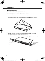
Страница 18: ...50 mm 17 5 8 inches long 1 Remove the rubber feet x4 on the bottom of the extension receiver Rubber feet 2 Use the included rack bracket screws x4 to attach the rackmount brackets to both sides of the extension receiver Rack bracket screws torque 0 88 N m to 1 08 N m 9 0 kgf cm to 11 0 kgf cm Rackmount bracket Both sides Rack bracket screws x4 PUQX1022YAV6_WX SE200P_OI_en fr indb 18 2022 03 23 10 ...

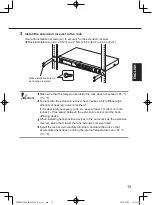
Страница 19: ...iver near devices which diffuse large amounts of heat eg power amplifiers If it is absolutely necessary to do so leave at least 1 U 44 mm 1 3 4 inches of free space between the extension receiver and the heat diffusing device When installing heat sensitive devices in the same rack as the extension receiver place them lower than the extension receiver itself Install the rack at well ventilated loca...

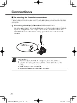
Страница 20: ...from the wire to expose the conductor Twist the conductor and insert it into the Euroblock connector Finally tighten the screws on the Euroblock connector 7 mm 1 mm 1 4 inches 1 16 inches memo Important Cable specifics Recommended cable AWG 16 to 28 do not use soldered cables Length of the coating to be removed 7 mm 1 mm 1 4 inches 1 16 inches Screw diameter 2 mm 1 16 inches Make sure that the wir...

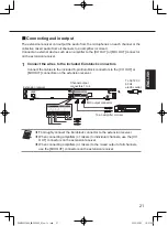
Страница 21: ... Euroblock connectors to the CH OUT or MIX OUT connectors on the extension receiver To AC120 V 60 Hz electric outlet Channel output connectors 1 to 4 MIX output connector To an amplifier or mixer Extension receiver memo Important Thoroughly connect the Euroblock connector to the extension receiver When connecting amplifiers or mixers to individual channels use the CH OUT connectors on the extensio...

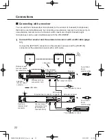
Страница 22: ...tension receiver and the RCVR IN connector on the extension receiver with a LAN cable Receiver Antenna 8 Antenna 2 Antenna 1 Wireless receiver connector inside the connector cover LAN cable LAN cable Wireless antenna connectors 1 to 8 Channel output connectors 1 to 4 Channel output connectors 1 to 4 correspond to channels 5 to 8 To AC120 V 60 Hz electric outlet To AC120 V 60 Hz electric outlet MIX...

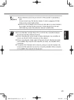
Страница 23: ... cable no longer than 0 5 m 1 6 ft for the connection between the receiver and the extension receiver When connecting the audio of each channel individually to an amplifier or mixer use the CH OUT connectors on this product When connecting the mixed output of the audio of each channel and audio of the AUDIO IN connector to an amplifier or mixer use the MIX OUT connectors The audio of all channels ...

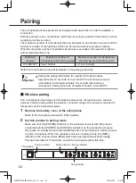
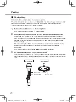
Страница 24: ...ly within approximately 10 seconds after pairing a microphone Pairing cannot be completed if power is turned OFF Wireless pairing Pair a microphone via wireless communication between the microphone and a wireless antenna Perform pairing within the wireless connection range of the antenna connected to this product via the extension receiver 1 Remove the battery cover of the microphone Refer to the ...

Страница 25: ...hone is too far away from the antenna or under bad connection conditions WX ST200P WX ST400P Power indicator Register button Power indicator 4 Place the battery cover back onto the microphone Refer to the microphone manual for further details memo Important The REG button is invalid if the channel to which microphone is paired and if that microphone is in use Turn the currently paired microphone p...

Страница 26: ...tor on the microphone with a conversion cable micro type B male to type A female locally procured and a USB 2 0 cable type A male to micro type B male locally procured When connecting the cables make sure that the conversion cable is attached to the receiver If you connect the cables otherwise you will not be able to pair the microphone Refer to the receiver manual for the detailed connection proc...

Страница 27: ...ed successfully the PWR indicator on the microphone will blinks red This product Pairing indicator Power indicator Pairing button Status indicator 5 Unplug the microphone from the receiver Unplug the cables connecting the microphone to the receiver If pairing has been completed successfully the microphone starts transmitting audio 6 Place the battery cover back onto the microphone Refer to the mic...

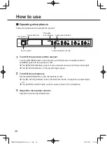
Страница 28: ...itch on this product to ON The POWER indicators green on the extension receiver and this product light The STATUS indicator on this product lights green 2 Turn ON the microphone Set the POWER switch on the microphone to ON The RF LEVEL indicator of the channel to which the microphone is paired lights on The AUDIO indicator lights on when audio is input to the microphone 3 Adjust the microphone vol...

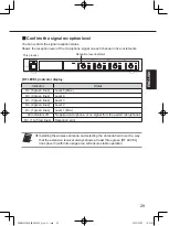
Страница 29: ... lines Level 4 On 3 green lines Level 3 On 2 green lines Level 2 On 1 green lines Level 1 Min All indicators off No paired microphone or no signal from the paired microphones On 1 to 5 red lines Reception error memo Important Installing the wireless antenna and selecting the antenna field in such a way that the extension receiver always shows at least three green RF LEVEL lines level 3 within its ...

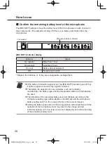
Страница 30: ... MIC BATT indicator goes off but it lights on again as soon as the signal is restored The battery life depends on many variables such as the battery manufacturer the battery type and the temperature within with the batteries are used The indication of the remaining battery level will changes according to the microphone battery type either alkaline or Ni MH set with the microphone battery setting s...

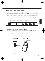
Страница 31: ...tely for five seconds This product Register indicator Power indicator Register button Status indicator 2 Check the PWR indicator on the microphone While the extension receiver is in pairing confirmation mode the PWR indicators of the powered on microphones paired with the channel which is in pairing confirmation mode will turn green and orange alternately This allows to confirm the channel microph...

Страница 32: ...tion will do nothing The pairing confirmation can also be performed from the microphone The microphone audio will keep on transmitting during pairing confirmation Also refer to the microphone manual When the REG indicator on the extension receiver blinks red during pairing confirmation mode there is no microphone paired with that channel Perform the steps described in Pairing page 24 PUQX1022YAV6_...

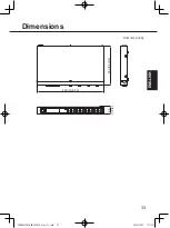
Страница 33: ...33 ENGLISH Dimensions Unit mm inch 420 16 9 16 250 9 13 16 44 1 3 4 PUQX1022YAV6_WX SE200P_OI_en fr indb 33 2022 03 23 10 21 41 ...

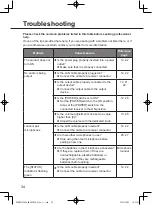
Страница 34: ...ce 14 21 22 Is the POWER switch set to ON Set the POWER switch to the ON position Also set the POWER switch on the connected receiver to the ON position 12 28 Is the volume adjustment knob set to a value higher than 0 Adjust the volume with the dedicated knob 13 28 I cannot pair microphones Is the LAN cable properly inserted Connect the cable to a receiver connector 14 22 Are there other microphon...

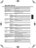
Страница 35: ...tor Euroblock Output characteristics 10 dBV equilibrium 600 Ω Mix output connector Connector Euroblock Output characteristics 10 dBV equilibrium 600 Ω Display indicators Common Power status Per channel Reception level 5 steps audio level mute microphone battery pairing Operating temperature range 0 C to 45 C 32 F to 113 F Operating humidity range 10 to 90 no condensation Dimensions Approx 420 mm W...

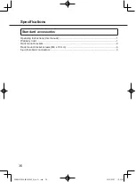
Страница 36: ...andard accessories Operating Instructions this manual 1 Warranty Card 1 Rack mount brackets 2 Rack mount bracket screws M4 x 10 mm 4 6 pin Euroblock connectors 3 PUQX1022YAV6_WX SE200P_OI_en fr indb 36 2022 03 23 10 21 41 ...

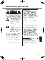
Страница 37: ...connecter l alimentation principale de tous les appareils AVERTISSEMENT Pour éviter les risques d incendie et ou de choc électrique n exposez pas l appareil à la pluie ou à l humidité L appareil ne doit pas recevoir de gouttes ou être aspergé et des objets remplis de liquide tels que des vases ne doivent pas être posés sur l appareil La prise de distribution électrique principale ou un coupleur d ...

Страница 38: ...onformément au manuel d instructions peut causer des interférences nuisibles aux communications radio L utilisation de cet équipement dans une zone résidentielle est susceptible de causer des interférences nuisibles auquel cas l utilisateur devra corriger les interférences à ses propres frais Pour les États Unis Le numéro de modèle et le numéro de série de ce produit se trouvent sur la surface de ...

Страница 39: ...ppareil 9 N utiliser que les accessoires recommandés par le fabricant 10 Ne placer l appareil que dans une baie un socle un trépied un support ou une table recommandé e par le fabricant ou vendu e avec l appareil Déplacer la baie ou le support avec le plus grand soin afin d en éviter le renversement 11 Débrancher cet appareil pendant les orages ou quand il n est pas utilisé pendant de longues péri...

Страница 40: ... En fonction des appareils raccordés la sortie audio peut être sélectionnée comme sortie isolée des canaux ou comme sortie de mixage Limitation de responsabilité CETTE PUBLICATION EST FOURNIE EN L ÉTAT SANS GARANTIE D AUCUNE SORTE EXPRESSE OU IMPLICITE Y COMPRIS MAIS SANS S Y LIMITER LES GARANTIES IMPLICITES DE QUALITÉ MARCHANDE D ADAPTATION À UN USAGE PARTICULIER OU DE NON VIOLATION DES DROITS DU...

Страница 41: ... QU UN DYSFONCTIONNEMENT DU SYSTÈME UN DÉFAUT UNE CONFIGURATION OU UNE INSTALLATION E TOUT PROBLÈME DÉSAGRÉMENT CONSÉCUTIF OU PERTE OU DOMMAGE SURVENANT DU SYSTÈME COMBINÉ AVEC DES DISPOSITIFS DE TIERS Droits d auteur La distribution la copie le démontage la compilation inverse et l ingénierie inverse du logiciel fourni avec ce produit sont tous expressément interdits En outre l exportation de tou...

Страница 42: ...rack 53 Connexions 55 Connexion des connecteurs Euroblock 55 Connexion de la sortie audio 56 Connexion d un récepteur 57 Appairage 59 Appairage sans fil 59 Appairage filaire 61 Utilisation 63 Utilisation des microphones 63 Confirmer le niveau de réception de signal 64 Confirmer le niveau de pile restant du microphone 65 Confirmer les microphones jumelés 66 Dimensions 68 Diagnostic des pannes 69 Sp...

Страница 43: ...ectuer la maintenance Le non respect de cette consigne peut provoquer des chocs électriques Enlever régulièrement la poussière de la prise électrique L isolation d une prise poussiéreuse pourrait échouer quand elle est soumise à des éléments tels que l humidité ce qui peut provoquer un incendie ou des chocs électriques Retirez le cordon d alimentation et nettoyez le avec un chiffon sec Si le produ...

Страница 44: ...ise d alimentation en les cassant en les manipulant en les rapprochant des sources de chaleur en les pliant excessivement en les tordant en les tirant en y plaçant des objets lourds en les attachant etc L utilisation d un cordon d alimentation ou d une prise d alimentation endommagés peut provoquer des chocs électriques des courts circuits ou des incendies Confiez la réparation du cordon d aliment...

Страница 45: ...eur d extension Débranchez le cordon d alimentation de la prise de courant pour couper complètement le flux de courant vers le récepteur d extension Alimentation électrique Le récepteur d extension utilise une alimentation CA 120 V 60 Hz Connectez le récepteur d extension à une source d alimentation d une capacité suffisante Connectez le cordon d alimentation à la source d alimentation de l une de...

Страница 46: ...nements La condensation est susceptible d apparaître dans les scénarios suivants Humidité élevée Passer d un endroit froid à un endroit chaud ou humide Si de la condensation apparaît attendez une à deux heures et assurez vous que toute la condensation a disparu avant de mettre l équipement sous tension Maintenance Effectuez cette opération après avoir mis le produit hors tension Cela pourrait entr...

Страница 47: ...ne affiche toujours au moins trois lignes vertes niveau 3 dans sa zone d utilisation garantissent un fonctionnement stable Allumé 5 lignes vertes Niveau 5 Max Allumé 4 lignes vertes Niveau 4 Allumé 3 lignes vertes Niveau 3 Allumé 2 lignes vertes Niveau 2 Allumé 1 ligne verte Niveau 1 Min Allumé 1 à 5 lignes rouges Erreur de réception Tous éteints Pas de microphone jumelé ou pas de signal du microp...

Страница 48: ...outon REG pressé pendant plus de deux secondes pour accéder au mode appairage page 59 Quittez le mode appairage en appuyant un court moment sur le bouton REG une fois en mode appairage Un canal ne peut pas entrer en mode appairage quand les microphones jumelés à ce canal sont actuellement actifs Confirmation de l appairage Appuyez un court moment sur le bouton REG pour passer en mode de confirmati...

Страница 49: ...ntrée audio externe à mixer et à envoyer vers le connecteur de sortie de mixage MConnecteur de sortie de mixage MIX OUT 10 dBV 600 Ω Sortie audio obtenue en mixant l audio de chaque canal avec l entrée audio du connecteur AUDIO IN NConnecteur SIGNAL GND SIGNAL GND Rassemble les SIGNAL GND venant d appareils externes pour éliminer la différence de potentiel électrique OCordon d alimentation Branche...

Страница 50: ...e utilisation à l intérieur uniquement Il ne peut pas être utilisé en extérieur Évitez d exposer le produit à la lumière directe du soleil pendant de longues périodes et ne l installez pas près d un climatiseur ou d un appareil de chauffage Le non respect de cette consigne pourrait altérer la forme et la couleur du produit et provoquer un dysfonctionnement Évitez également l exposition aux gouttel...

Страница 51: ...e humidité très élevée Endroits contenant de grandes quantités de vapeur ou de graisse comme les cuisines Près des haut parleurs des téléviseurs des aimants et d autres sources magnétiques puissantes Surfaces inclinées Où il y a un risque de dommage par de l eau de mer ou des gaz corrosifs Lors de l installation dans un rack Lors de l installation du récepteur d extension dans un rack utilisez l u...

Страница 52: ... d installer le produit déchargez vous en touchant un objet métallique mis à la terre afin d éviter les dommages causés par l accumulation d électricité statique Vis de serrage Serrez les vis bien droit Après avoir serré les vis vérifiez visuellement qu elles sont droites et bien serrées N utilisez pas de tournevis à percussion ou de tournevis électrique car même ceux avec embrayages rendent diffi...

Страница 53: ...ng 1 Retirer les pieds en caoutchouc x4 sur le dessous du récepteur d extension Pieds en caoutchouc 2 Utiliser les vis de fixation x4 fournies pour fixer les supports de montage en rack des deux côtés du récepteur d extension Couple des vis de support d installation en rack 0 88 N m à 1 08 N m 9 0 kgf cm à 11 0 kgf cm Support de montage en rack Les deux côtés Vis du support de rack x4 PUQX1022YAV6...

Страница 54: ... à proximité d appareils qui diffusent de grandes quantités de chaleur ex amplificateurs de puissance S il est absolument nécessaire de le faire laissez au moins 1 U 44 mm 1 3 4 po d espace libre entre le récepteur d extension et le diffuseur de chaleur Lors de l installation des appareils thermosensibles dans le même rack que le récepteur d extension placez les plus bas que le récepteur d extensi...

Страница 55: ... de revêtement du fil pour exposer le conducteur Torsadez le conducteur et insérez le dans le connecteur Euroblock Enfin serrez les vis du connecteur Euroblock 7 mm 1 mm 1 4 pouces 1 16 pouces note Important Spécificités des câbles Câble recommandé AWG 16 à 28 ne pas utiliser de câbles soudés Longueur du revêtement à enlever 7 mm 1 mm 1 4 pouces 1 16 pouces Diamètre de vis 2 mm 1 16 pouces Assurez...

Страница 56: ...ou MIX OUT du récepteur d extension Vers la prise de courant électrique CA 120 V 60 Hz Connecteurs de sortie de canal 1 à 4 Connecteur de sortie MIX Vers un amplificateur ou un mélangeur Récepteur d extension note Important Connectez avec précaution le connecteurs Euroblock au récepteur d extension Quand vous connectez des amplificateurs ou des mélangeurs à des canaux individuels utilisez les conn...

Страница 57: ...xtension via un câble LAN Récepteur Antenne 8 Antenne 2 Antenne 1 Connecteur du récepteur sans fil à l intérieur du cache du connecteur Câble LAN Câble LAN Connecteurs d antenne sans fil 1 à 8 Connecteurs de sortie de canal 1 à 4 Vers la prise de courant électrique CA 120 V 60 Hz Vers la prise de courant électrique CA 120 V 60 Hz Connecteur de sortie MIX Connecteur de sortie MIX Récepteur d extens...

Страница 58: ... un câble LAN ne dépassant pas 0 5 m 1 6 pi pour connecter le récepteur et le récepteur d extension Lors de la connexion individuelle de l audio de chaque canal sur un amplificateur ou un mélangeur utilisez les connecteurs CH OUT de ce produit Lors de la connexion de la sortie mixée de l audio de chaque canal et de l audio du connecteur AUDIO IN sur un amplificateur ou un mélangeur utilisez les co...

Страница 59: ...nt dans les 10 secondes environ après avoir jumelé un microphone L appairage ne peut pas être terminé si le récepteur est mis hors tension Appairage sans fil Jumelez un microphone via la communication sans fil entre le microphone et une antenne sans fil Effectuez l appairage dans la plage de connexion sans fil de l antenne connectée à ce produit via le récepteur d extension 1 Retirer le couvercle ...

Страница 60: ...on est mauvais WX ST200P WX ST400P Voyant d alimentation Bouton d enregistrement Voyant d alimentation 4 Remettre le couvercle du compartiment des piles sur le microphone Reportez vous au manuel du microphone pour plus de détails note Important Le bouton REG n est pas valide si le canal auquel le microphone est jumelé est utilisé Mettez hors tension le microphone actuellement jumelé puis jumelez u...

Страница 61: ...âble de conversion mâle micro type B à femelle type A à se procurer localement et un câble USB 2 0 mâle type A à mâle micro type B à se procurer localement Lors de la connexion des câbles assurez vous que le câble de conversion est bien fixé au récepteur Si d autres câbles sont connectés le microphone ne pourra pas être jumelé Reportez vous au manuel du récepteur pour connaître la procédure de con...

Страница 62: ...en rouge Ce produit Voyant d appairage Voyant d alimentation Bouton d appairage Voyant d état 5 Débrancher le microphone du récepteur Débranchez les câbles connectant le microphone au récepteur Si l appairage a été effectué avec succès le microphone commence à transmettre l audio 6 Remettre le couvercle du compartiment des piles sur le microphone Reportez vous au manuel du microphone pour plus de ...

Страница 63: ...roduit et l interrupteur POWER de ce produit sur ON Les voyants POWER verts du récepteur d extension et de ce produit s allument Le voyant STATUS de ce produit s allume en vert 2 Allumer le microphone Réglez l interrupteur POWER du microphone sur ON Le voyant RF LEVEL du canal auquel le microphone est jumelé s allume Le voyant AUDIO s allume quand l audio est entré dans le microphone 3 Ajuster le ...

Страница 64: ...Niveau 4 Allumé 3 ligne verte Niveau 3 Allumé 2 ligne verte Niveau 2 Allumé 1 ligne verte Niveau 1 Min Tous les voyants éteints Pas de microphone jumelé ou pas de signal des microphones jumelés Allumé 1 à 5 lignes rouges Erreur de réception note Important L installation de l antenne sans fil et la sélection du champ d antenne de sorte que le récepteur d extension affiche toujours au moins trois li...

Страница 65: ... BATT s éteint mais il s allume à nouveau dès que le signal est restauré La durée de vie de la pile dépend de nombreuses variables telles que le fabricant de la pile le type de pile et la température à l intérieur des piles utilisées L indication du niveau de pile restant change en fonction du type de pile alcaline ou Ni MH du microphone sélectionné avec l interrupteur de réglage de pile du microp...

Страница 66: ...vement pendant cinq secondes Ce produit Voyant d enregistrement Voyant d alimentation Bouton d enregistrement Voyant d état 2 Vérifier le voyant PWR sur le microphone Quand le récepteur d extension est en mode de confirmation de l appairage le voyant PWR des microphones sous tension jumelés avec le canal en mode de confirmation de l appairage passe du vert à l orange alternativement Ceci permet de...

Страница 67: ...ion de l appairage peut également être effectuée à partir du microphone L audio du microphone sera maintenu lors de la transmission pendant la confirmation de l appairage Reportez vous également au manuel du microphone Quand le voyant REG du récepteur d extension clignote en rouge pendant le mode de confirmation de l appairage aucun microphone n est jumelé à ce canal Effectuez les étapes décrites ...

Страница 68: ...68 Dimensions Unité mm po 420 16 9 16 250 9 13 16 44 1 3 4 PUQX1022YAV6_WX SE200P_OI_en fr indb 68 2022 03 23 10 21 46 ...

Страница 69: ...7 L interrupteur POWER est il réglé sur ON Réglez l interrupteur POWER sur la position ON Réglez également l interrupteur POWER du récepteur connecté sur la position ON 47 63 Le bouton de réglage est il réglé sur une valeur supérieure à 0 Ajustez le volume sonore avec le bouton de réglage dédié 48 63 Je ne peux pas jumeler les microphones Le câble LAN est il correctement inséré Connectez le câble ...

Страница 70: ...onnecteur Euroblock Caractéristique de la sortie 10 dBV equilibrium 600 Ω Connecteur de sortie mix Connecteur Euroblock Caractéristique de la sortie 10 dBV equilibrium 600 Ω Affichage voyants Commun Alimentation état Par canal Niveau de réception 5 niveaux niveau audio sourdine pile de microphone appairage Plage de température de fonctionnement 0 C à 45 C 32 F à 113 F Plage d humidité de fonctionn...

Страница 71: ...d Instructions d utilisation ce manuel 1 Carte de garantie 1 Supports de montage en rack 2 Vis de supports de montage en rack M4 x 10 mm 4 Connecteurs Euroblock 6 broches 3 PUQX1022YAV6_WX SE200P_OI_en fr indb 71 2022 03 23 10 21 46 ...

Страница 72: ...ct will not be covered by the warranty Panasonic Corporation of North America Two Riverfront Plaza Newark NJ 07102 5490 https na panasonic com us Panasonic Canada Inc 5770 Ambler Drive Mississauga Ontario L4W 2T3 Canada 1 877 495 0580 https www panasonic com ca Panasonic Connect Co Ltd 2022 pav0421 1042 PUQX1022YA Printed in Vietnam PUQX1022YAV6_WX SE200P_OI_en fr indb 72 2022 03 23 10 21 46 ...

Отзывы: