

Installation
The installation tasks are explained using 5 steps.
Step1
Make sure all items are prepared
before beginning installation.
Step2
Mount the brackets to a ceil-
ing or wall.
Step3
Connect cables, and then attach
the camera to the mount bracket.
Step4
Adjust the angle of view and focus,
and then mount the enclosure.
Step1 Preparations
Step3 Mount the camera to the attachment plate
Step5 Configure the network settings
There are 4 methods to install the camera to a ceiling or wall as described below. Prepare the
required parts for each installation method before starting the installation. The following are the
requirements for the various installation methods.
Installation method
Recommend-
ed screw
Minimum pull-
out strength
(per 1 pc.)
(1) Mount the camera on the two-gang junction box using
the attachment plate.
M4 screws x 4
196 N {44 lbf}
(2) Directly mount the camera onto the ceiling or wall us-
ing the attachment plate (when wiring can be installed
in the ceiling or wall).
M4 screws x 4
196 N {44 lbf}
(3) Mount the camera in the ceiling using WV-Q174B ceil-
ing mount brackets (approx. 280
g
{0.62 lbs}).*
1
—
There is suf-
ficient strength in
the ceiling
(4) When mounting the camera on an insufficiently strong
ceiling using the WV-Q105 ceiling mount brackets (ap-
proximately 150
g
{0.33 lbs})*
1
anchor bolt x 2
*2
*1 For information on mounting the camera using WV-Q174B or WV-Q105, refer to the In-
struction Manual provided with the WV-Q174B or WV-Q105.
*2 Make sure that the installed mount bracket can support more than 5 times of the weight of
the camera.
IMPORTANT:
● Procure 4 screws (M4) to secure the attachment plate (accessory) to a ceiling or a
wall.
● The minimum required pull-out capacity of a single screw or anchor bolt is 196 N
{44 lbf} or more when mounting with the installation method [1] and [2] above.
● When mounting the camera on a concrete ceiling, use an AY plug bolt (M4) for securing.
(Recommended tightening torque: 1.6 N·m {1.18 lbf·ft})
● Select screws according to the material of the ceiling that the camera will be mounted
to. In this case, wood screws and nails should not be used.
● If a ceiling board such as plaster board is too weak to support the total weight, the
area shall be sufficiently reinforced.
(2) Using the Attachment plate (accessory)
q
Loosen 2 enclosure fixing screws
of the enclosure.
When installing the camera directly on the ceil-
ing or wall with cables exposed, or when
mounting the camera using the ceiling mount
bracket WV-Q174B (option), cut out a portion of
the dome cover to open a cable access hole.
w
Remove the enclosure from the camera.
e
Connect cables to the camera according to the
instructions in “Making connections”, and temporar-
ily fix the camera by inserting attachment mounting
screws into the holes of the attachment plate.
r
Secure the camera using the
camera fixing screws.
Camera fixing screw
Attachment mounting screws
Tab of the attachment plate
Side cable access hole
Note:
● Loosen 2 enclosure fixing screws using
the bit (accessory).
Note:
● After cables have been connected to the camera, align the OPEN mark of the cam-
era side panel with the tab of the attachment plate, insert 2 attachment mounting
screws into the attachment plate, and rotate the camera by approximately 15°. The
LOCK mark is moved to the tab position of the attachment plate and the camera is
temporarily secured.
IMPORTANT:
● Disconnect either the 12 V DC power source or
PoE power source to prevent power from being
supplied during mounting work.
IMPORTANT:
● Be sure to tighten the camera fixing
screw. Failure to observe this may cause
camera trouble due to camera falling.
(Recommended tightening torque:
0.78 N·m {0.58 lbf·ft})
●
●
Do not remove the auxiliary wire.
SF R 311
SF R310
●
●
The camera is fixed only with special screws. Please be
careful about the handling when you wish to remove.
SF N 311
SF N 310
Using the side cable access hole
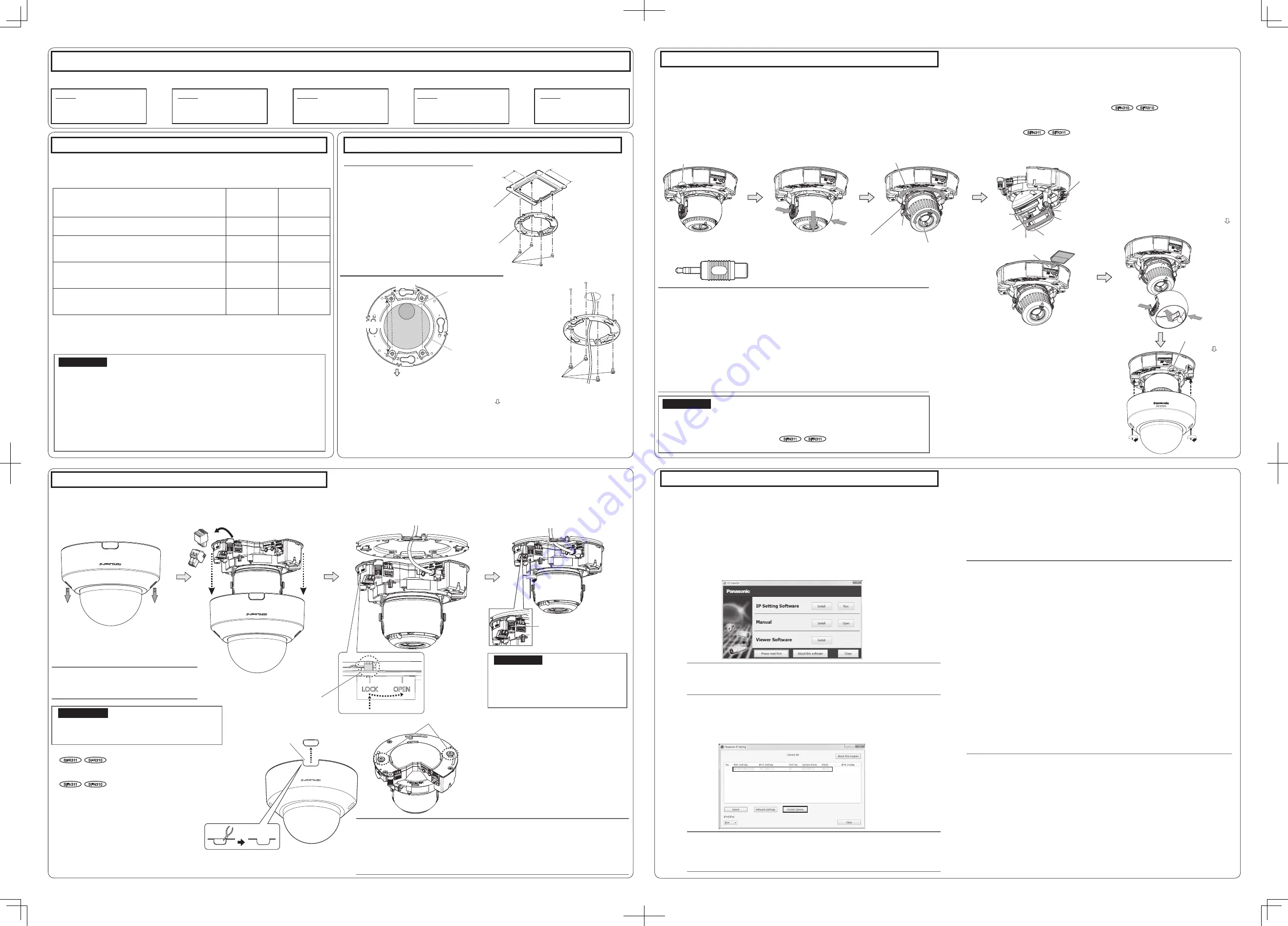
Step4 Adjustment
q
Turn on power for the camera by either con-
necting a LAN cable or a 12 V DC power cable.
w
Connect the MONITOR OUT conversion plug
(accessory) to the MONITOR OUT terminal of
the camera, and then connect the monitor for ad-
justment with a RCA pin cable (locally procured).
● The camera is set to be connected to the NTSC
monitor for adjustment at factory shipment.
e
Press the PUSH position on both sides of
the inner dome and remove the inner dome.
The following are descriptions for when the camera with default settings is configured. If you are using fire-
wall software on your PC, the Setup Program may not be able to find any cameras on your network.
Configure the setting of the camera after temporarily invalidating the firewall software. Contact the network
administrator or your Internet service provider for information about configuring the settings of the network.
q
Insert the provided CD-ROM into the CD-ROM drive of your PC.
w
Click the [Run] button next to [IP Setting Software].
[Panasonic IP Setting] screen will be displayed. When a camera is found, information
about it, such as its MAC address and IP address, is displayed.
e
Select the camera you want to configure, and click [Access Camera].
r
Adjust the angle of the camera with the tilt
table, pan table, and azimuth adjustment ring.
Horizontal position (Panning): ±180°
Vertical position (Tilting): ±85°
Image tilt adjustment:
-225°(Left) to +120°(Right)
Tighten the cross slot tilting lock screw.
(Recommended tightening torque:
0.59 N·m {0.44 lbf·ft})
t
Adjust the zoom and focus while performing Step
r
.
you can press the FOCUS ASSIST button
to open the FOCUS ASSIST adjustment
screen and obtain the optimum focal
length. Then, tighten the focus knob.
SF N 310
SF R310
y
Insert an SD memory card into the slot, if
necessary.
● Insert the SD memory card with its label
facing down.
● For information about performing the SD
memory card setting, refer to the Operat-
ing Instructions (included in the CD-ROM).
u
Press the PUSH position on both sides of
the inner dome and install the inner dome to
the place where it was removed.
i
Disconnect the monitor for adjustment.
Attach the enclosure.
(Attach the enclosure by aligning the Pana-
sonic logo to the direction marker (FRONT )
on the camera.)
● Loosen the zoom knob and move the
knob between TELE and WIDE to obtain
the appropriate angle of view. Then,
tighten the zoom knob.
● Move the focus knob between FAR and
NEAR to obtain the appropriate focal
length. Press the AF button to activate the
auto focus function.
SF N 311
SF R 311
Loosen the focus knob and move the knob
between FAR and NEAR. Alternatively,
Note:
● Depending on the adjustable range or the optical zoom, it must be noted that the
shadow of the enclosure may be projected.
● When mounting the camera on a ceiling, adjust the tilt angle so that the TOP mark
above the lens always comes to the top side.
● When the camera is installed to a wall, rotate the azimuth adjustment ring till the
TOP mark above the lens always comes to the top side.
● When adjusting the viewing angle for cameras mounted to ceilings, the enclosure
and installation auxiliary wire may be displayed on the screen depending on the
direction the camera is facing. Move the enclosure and installation auxiliary wire so
that they are not displayed on the screen.
● Remove the camera using the reverse order of the installation procedures.
Note:
● Refer to “Using the CD-ROM” in the Operating Instructions on the provided
CD-ROM for further information about CDLauncher.
Note:
● When no image is displayed on the “Live” page, refer to the Troubleshooting in
the Operating Instructions on the provided CD-ROM.
● It is possible to enhance the network security by encrypting the access to camer-
as using the HTTPS function. Refer to the Operating instructions on the provided
CD-ROM for how to configure the HTTPS settings.
● Click the [Setup] button on the “Live” page, the user authentication window will be
displayed. Enter the default user name and password as follows, and log in.
User name: admin
Password: 12345
● When changing settings related to the network settings, such as connection
mode, IP address, and subnet mask, click the [Network Settings] button in
[Panasonic IP Setting] screen as shown in step
e
, then change each setting.
● Due to security enhancements in “IP Setting Software”, “Network settings” of the
camera to be configured cannot be changed when around 20 minutes have
passed after turning on the power of the camera. (When the effective period is set
to “20 min” in the “Easy IP Setup accommodate period”.)
However, settings can be changed after 20 minutes for cameras in the initial set
mode.
● “Network Camera Recorder with Viewer Software Lite” which supports live moni-
toring and recording images from multiple cameras is available. For further infor-
mation, refer to our website
(http://security.panasonic.com/pss/security/support/info.html).
Note:
● When cameras are displayed in [Panasonic IP Setting] screen, click the cam-
era with same MAC address as the MAC address printed on the camera that
you want to configure.
IMPORTANT:
● Securely tighten all the enclosure fixing screws (x2) of enclosure. Otherwise, camera
dropping may result in injury. (Recommended tightening torque: 0.59 N·m {0.44 lbf·ft})
● Defocus may be caused by the reinstalled enclosure. In this case, perform the auto
focus function from the setup menu.
SF N 311
SF R 311
● Remove the cover film from the dome cover.
Configuring the camera so that it can be accessed from a PC
r
If the installation screen of the viewer software “Network Camera View 4S” is displayed,
follow the instructions of the wizard to start the installation. (The viewer software is in-
stalled from the camera.)
● The License Agreement will be displayed. Read the Agreement and choose “I accept
the term in the license agreement”, and click [OK].
● The launcher window will be displayed. If the launcher window is not displayed, double
click the “CDLauncher.exe” file on the CD-ROM.
● The “Live” page will be displayed.
● If you cannot install the viewer software “Network Camera View 4S” or if images are not
displayed, click the [Install] button next to [Viewer Software] on the launcher window to
install the software.
● Perform the [Time & date] settings in the “Setup” - “Basic” page before using the camera.
Step5
Configuring the camera so that
it can be accessed from a PC.
Step2 Fixing the attachment plate
(1) Using a two-gang junction box
Attachment plate (accessory)
Fixing screws for
attachment plate: x4
(M4, locally procured)
● If the mounting direction of the camera has already been determined
Align the FRONT direction (the direction of FRONT marker on the camera that indicates the
installation direction when installing the camera) of
©
template A with the desired direction, and
drill through a 25.4 mm {1 inch} diameter hole.
● If the mounting direction of the camera is not determined yet or if you want to change
the direction of the camera after it has been installed
If you want to be able to change the direction of the camera, drill through a 73 mm {2-7/8 inches} diameter
hole in the center. By doing so you can adjust the mounting direction of the camera in 90° increments.
Ⓕ
MONITOR OUT conversion plug
(accessory)
● To remove the SD memory card, hold down
the SD ON/OFF button for about 2 seconds.
When the flashing SD MOUNT indicator goes
out, you can remove the SD memory card.
● After the SD memory card has been replaced,
press the SD ON/OFF button, and make sure
the SD MOUNT indicator is continually lit.
● If you do not press the SD ON/OFF button
after replacing the SD memory card, the
SD MOUNT indicator is continually lit
approximately 5 minutes later.
● Remove the external I/O terminal plug
and power cord plug attached to the
camera.
46 mm {1-13/16 inches}
83.5 mm {3-9/32 inches}
Two-gang junction box
Attachment plate (accessory)
Fixing screws for attachment plate: x4 (M4, locally procured)
Ø25.4 mm
{1 inch}
Ø73 mm
{2-7/8 inches}
FRONT
46 mm
83.5 mm
e
u
Azimuth adjustment ring
Pan table
Tilting lock screw
Tilt table
r
y
SD slot
NTSC
⇔
PAL
w
i
Direction marker
for installation
(FRONT )
Zoom knob
Focus knob
WIDE
NEAR
TELE
FAR
t
AF


