Important:
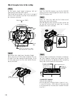
• When mounting the camera onto the camera mount
bracket, hold the base part of the camera. Mounting
the camera while holding the moving part may result
in malfunction.
Step 7
Fix the camera on the camera mount bracket (accessory)
using the camera fixing screw (accessory).
Recommended tightening torque:
0.68 N·m
{0.50 lbf·ft}
Step 8
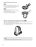
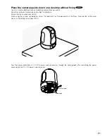
Connect the cables to the network connector and the
power inlet.
Important:
• When the power of the camera is turned on, the cam-
era will start panning and the position will automati-
cally be initialized.
• Do not touch the camera in the process of initializa-
tion. Otherwise, it may fail to initialize and may cause
malfunction.
• When the camera has been inadvertently touched
and moved after the initialization is complete, the pre-
set positions may be inaccurate. In this case, use the
position refresh function or restart the camera to cor-
rect the preset positions.
Refer to the Operating Instructions (PDF) for further
information.
• Network connector
Connect a LAN cable (category 5 or better, STP*) to the
network connector.
* PAL model only
Important:
• Use all 4 pairs (8 pins) of the LAN cable.
• The maximum cable length is 100 m {328 feet}.
• Make sure that the PoE device in use is compliant
with IEEE802.3af standard.
• When connecting both the 12 V DC power supply
and the PoE device for power supply, 12 V DC will be
used for power supply.
• When the LAN cable is disconnected once, reconnect
the cable after around 2 seconds. When the cable is
quickly reconnected, the power may not be supplied
from the PoE device.
Fixing screw
(accessory)
MONITOR OUT
AUDIO OUT
MIC/LINE IN
EXT I/O
4 3 2 1
12V IN
POWER
INITIAL
SET
ACT
LINK
10BASE-T/
100BASE-TX
Network connector
12 V DC power supply terminal
FRONT
OPEN
LOCK
20 °
Rotate
Camera mount bracket
(accessory)
Camera
Guide part
Center of the
camera mount bracket
Base part
Lock plate
Moving part
18
Содержание WV-SC384
Страница 39: ......

