background image

16

Note:

• [USER COLOR R], [USER COLOR G], and [USER

COLOR B] can be adjusted only if [User] has been cho-
sen for [COLOR TEMPERATURE]. 

v

To reset the video adjustment to the default, use the

C

/

D

buttons to select "NORMAL SETTINGS" and press

the menu button. 

The settings of only input signals (VIDEO, HDMI, and
PC) currently displayed are reset to the factory
default.

Screen setup 

The image position and size in contradistinction to the LCD
panel are adjusted. 

z

Press the menu button. The main menu screen appears.
(

page 15) 

x

Use the 

C

/

D

buttons to select "SCREEN SETUP", and

press the menu button.  

The screen setup menu appears. 

Present input signals are displayed in the menu title.
For VIDEO input: VIDEO 
For HDMI input: HDMI 
For PC input: PC 

An input signal type appears at the right of the menu title as
follows: 

• For VIDEO input

NTSC:When a video signal input of the NTSC system or

no signal is provided 

PAL : When a video signal input of the PAL system is

provided 

• For HDMI input

The present signal is displayed in the style of "scanning
system and refresh frequency" in accordance with the
timing data table (

page 11). 

• For PC input 

The present signal is displayed in the style of "resolution
and refresh frequency" in accordance with the timing
data table (

page 11). 

c

Use the 

C

/

D

buttons to select "AUTO", and press the

menu button. 

The automatic adjustment starts. 

Note:

• The screen flickers during automatic adjustments, but

this phenomenon is not a malfunction. 

• Automatic adjustment for VIDEO input makes the scan-

ning ratio 4:3 full.

• Automatic adjustment takes several seconds to over 10

seconds depending on the conditions of the video sig-
nal. 

If an optimal screen cannot be obtained after automatic
adjustment, the following operations may help: 

b

Select "EXIT", and press the menu button.

The main menu screen resumes.

n

Select "EXIT" on the main menu screen, and press the
menu button. 

The regular screen resumes. 

Note:

• The regular screen automatically resumes after no oper-

ation is performed for approximately 10 seconds.

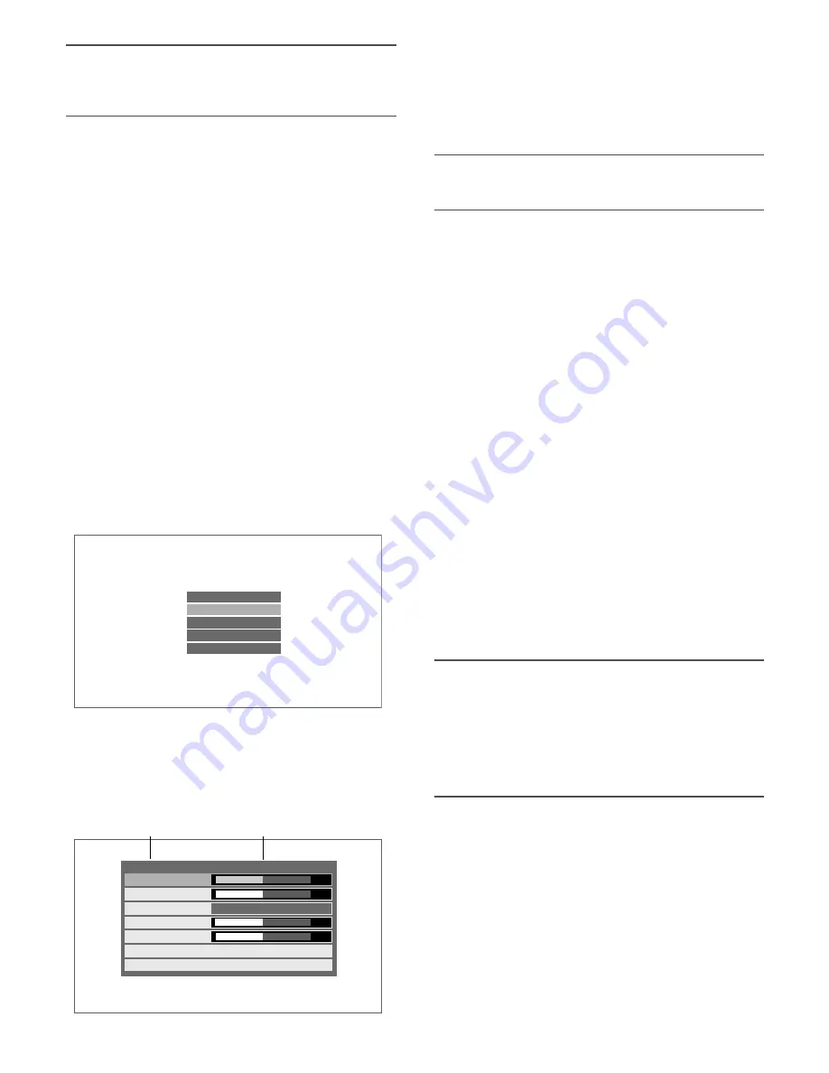
V I D E O       A D J U S T

S C R E E N   S E T U P

M A I N T E N A N C E

L A N G U A G E

E X I T

H-POSITION

V-POSITION

SCAN

CLOCK

PHASE

AUTO

EXIT

PC

00
00

00
00

1 2 8 0   x   1 0 2 4   @ 6 0   H z

16 : 9

Menu title

Input signal type

Содержание WV-LW1900

Страница 1: ...e instructions carefully and save this manual for future use No model number suffix is shown in this manual This illustration represents WV LW2200 Video Monitor WV LW2200 MENU SELECT AUDIO INPUT SELECT ECO Operating Instructions Video Monitor Model No WV LW1900 WV LW2200 ...

Страница 2: ... assure continued compliance example use only shielded interface cables when connecting to com puter or peripheral devices Any changes or modifications not expressly approved by the party responsible for compli ance could void the user s authority to operate this equip ment For U S A This Class A digital apparatus complies with Canadian ICES 003 For Canada The lightning flash with arrowhead symbol...

Страница 3: ...your outlet consult an electrician for replacement of the obso lete outlet 10 Protect the power cord from being walked on or pinched particularly at plugs convenience receptacles and the point where they exit from the apparatus 11 Only use attachments accessories specified by the manufacturer 12 Use only with the cart stand tripod bracket or table specified by the manufacturer or sold with the app...

Страница 4: ...OR THE IMPROVEMENTS OF THIS PUBLICATION AND OR THE CORRESPONDING PRODUCT S Disclaimer of warranty IN NO EVENT SHALL Panasonic Corporation BE LIABLE TO ANY PARTY OR ANY PERSON EXCEPT FOR REPLACEMENT OR REASONABLE MAINTENANCE OF THE PRODUCT FOR THE CASES INCLUDING BUT NOT LIMITED TO BELOW 1 ANY DAMAGE AND LOSS INCLUDING WITHOUT LIMITATION DIRECT OR INDIRECT SPECIAL CONSEQUENTIAL OR EXEMPLARY ARISING...

Страница 5: ...ion unit 12 Audio Volume Control 13 ECO Mode Activation Deactivation 14 ECO mode activation 14 ECO mode deactivation 14 Video Adjustment and Setup 15 Video adjustment 15 Screen setup 16 Language in the menus to be displayed 18 Operation time check 19 Installation 20 How to mount monitor stand 20 How to remove monitor stand mounting bracket 20 Screw holes for wall mounting bracket 20 Connections 21...

Страница 6: ...go and High Definition Multimedia Interface are trademarks or registered trademarks of HDMI Licensing LLC Precautions Refer all work related to the installation of this prod uct to qualified service personnel or system installers Do not block the ventilation opening or slots on the cover Do not drop metallic parts through slots This could permanently damage the apparatus Turn the power off immedia...

Страница 7: ...eptacle is used ensure that the ground resistance is 100 ohms or less Power supply Be sure to make the ground connection before connect ing the power plug of this product to the main power supply Also be sure to disconnect the ground after dis connecting the power plug of this product from the main power supply if necessary Any of the following circuit breaking methods should be selected for the p...

Страница 8: ...e of this monitor approximately 5 cm away from the wall Do not mount the monitor on places subject to constant vibrations That may cause trouble or damage Do not install this system in any place where it will be subjected to direct sunlight for a long time or close to any air conditioning equipment Failure to observe this may cause deformation discoloration failure or mal function Please keep this...

Страница 9: ...Menu button MENU Displays the main menu page 15 This button is also used to determine the selected parameter in the setup menus t Selection buttons SELECT C D ECO button These buttons move the cursor in setup menus C Down D Up The C button functions as the ECO button other than the setup menus to activate the ECO mode page 14 y Audio buttons AUDIO These buttons adjust the audio volume level These ...

Страница 10: ... refer to page 11 Timing data chart for HDMI input 5 PC input connector PC IN Accepts an analog RGB signal from a PC For timing data this connector supports refer to page 11 Timing data chart for PC input 6 VIDEO input connector VIDEO IN Accepts a composite video signal from an external device 7 Video output connector VIDEO OUT Supplies a composite video signal accepted by the VIDEO IN connector t...

Страница 11: ... 500 31 5 37 9 60 72 640 x 480 31 500 37 5 75 36 000 35 1 56 800 x 600 40 000 37 9 60 50 000 48 1 72 49 500 46 9 75 65 000 48 4 60 1024 x 768 75 000 56 5 70 78 750 60 0 75 108 000 67 5 75 1152 x 864 108 000 60 0 60 1280 x 960 108 000 135 000 74 250 85 500 64 0 80 0 45 0 47 7 60 1280 x 1024 1280 x 720 1360 x 768 25 175 CEA standard CEA standard CEA standard CEA standard CEA standard CEA standard CE...

Страница 12: ...ote The ECO mode backlight off page 14 is automati cally activated after no input signal is provided for 10 seconds or more If an input signal is provided in the ECO mode the backlight automatically lights and the regular mode is activated When the screen display is not proper with the PC input selected refer to the table in page 11 to perform the out put setting of the connected PC If an input si...

Страница 13: ...ttons AUDIO during image display allows users to adjust the audio volume level When the button is pressed the volume level appears on the bottom of the screen Audio volume down Audio volume up VOLUME 22 Item Effect Setting value Volume Down Up 0 40 ...

Страница 14: ...ctivation z Press the D button during image display The ECO mode is deactivated and the regular mode resumes Note Buttons other than C and D buttons can deactivate the ECO mode However the function assigned to the but ton to be pressed is also performed Example Pressing the menu button in the ECO mode deactivates the ECO mode and then the main menu screen appears The ECO mode backlight off is auto...

Страница 15: ...d in the style of resolution and refresh frequency in accordance with the timing data table page 11 Note The respective setting items are allowed to set up differ ent values in regard to each input signal TINT can be adjusted only if the input signal is of the NTSC system or HDMI c Use the C D buttons to select the item to be adjusted and press the buttons to adjust the screen V I D E O A D J U S ...

Страница 16: ...le of scanning system and refresh frequency in accordance with the timing data table page 11 For PC input The present signal is displayed in the style of resolution and refresh frequency in accordance with the timing data table page 11 c Use the C D buttons to select AUTO and press the menu button The automatic adjustment starts Note The screen flickers during automatic adjustments but this phenom...

Страница 17: ... are not used 4 3 zoom 4 3 zoom The image without surrounding areas is displayed with the aspect ratio of 4 3 The far right and far left portions of the screen are not used 16 9 16 9 full 16 9 full The whole image is displayed on the whole screen 16 9 zoom 16 9 zoom The image without surrounding areas is displayed on the whole screen Dot by dot Dot by dot ー The whole image is displayed with one to...

Страница 18: ... v Select EXIT and press the menu button The main menu screen resumes Note When any language other than English is selected the menu title and EXIT are described in the selected lan guage b Select EXIT on the main menu screen and press the menu button The regular screen resumes Note The regular screen automatically resumes after no oper ation is performed for approximately 10 seconds V I D E O A D...

Страница 19: ...d The power cord or power plug is abnormally hot A flaw or a scratch is observed An abnormal event or trouble other than the above is observed cPress the menu button The main menu screen resumes v Select EXIT on the main menu screen and press the menu button The regular screen resumes Note The regular screen automatically resumes after no oper ation is performed for approximately 10 seconds V I D ...

Страница 20: ...Monitor stand mounting bracket Monitor stand accessory Cushioning Protrusions Rectangular holes Mounting screw M4 Mounting screw M4 Stand cover Monitor stand mounting bracket How to remove monitor stand mounting bracket z Remove 1 piece of the stand cover mounting screw M4 x 15 and then remove the stand cover x Remove 4 pieces of the screws M4 x 15 securing the monitor stand mounting bracket and t...

Страница 21: ...Another video monitor PC PC output Video input Digital disk recorder HDMI output Audio output Video output Power cord accessory Use a cord clamp to fasten the HDMI cable and power cord 21 Connections ...

Страница 22: ...eo monitors When plural video monitors are connected connect the VIDEO input connector of another video monitor to the video output connector of this monitor Use a coaxial cable for connection Up to 10 video monitors can be connected If 11 or more video monitors are connected image quality may be degraded The total length of each cable should not exceed 150 m Digital disk recorder connection To pl...

Страница 23: ... input jack Are the cables properly inserted into the connectors 10 21 Are the cables connected to the signal type compatible input connectors 10 21 When the PC input signal is not compliant with the specifications of this monitor no image is displayed Check the specifications of the connected PC 11 16 Perform automatic adjustment in the screen setup menu If the display position is not properly ad...

Страница 24: ...uring use The power cord gets hot when bent or stretched The power cord connectors or power plug is damaged Continued use of the damaged power cord connectors or power plug may cause electric shock or fire Remove the power plug from the outlet immediately and contact the dealer for repair Problem Cause Remedy ...

Страница 25: ...tal vertical synchronization TTL mini D sub 15 pin connector Audio input 8 dB Hi Z RCA pin jack Speaker output 0 5 W Ambient operating temperature 0 C 40 C 32 F 104 F Ambient storage temperature 20 C 60 C 4 F 140 F Ambient operating humidity Less than 90 Screw holes for wall mounting bracket 100 mm pitch compliant with VESA standards Dimensions WV LW1900 463 mm W x 374 mm H x 235 mm D 18 7 32 W x ...

Страница 26: ...5 32 100 3 15 16 100 3 15 16 233 9 3 16 321 12 5 8 53 2 3 32 374 14 23 32 15 5 463 18 7 32 265 10 7 16 30 1 3 16 48 1 27 32 MENU SELECT AUDIO INPUT SELECT ECO Video Monitor WV LW2200 15 5 531 20 7 8 215 5 8 15 32 215 5 8 15 32 361 14 7 32 414 16 5 16 78 3 1 16 30 1 3 16 48 1 27 32 235 9 1 4 100 3 15 16 100 3 15 16 233 9 3 16 53 2 3 32 265 10 7 16 ...

Страница 27: ...27 ...

Страница 28: ... 1 800 528 6747 Three Panasonic Way 2H 2 Secaucus New Jersey 07094 Panasonic Canada Inc 5770 Ambler Drive Mississauga Ontario L4W 2T3 Canada 905 624 5010 http www panasonic ca Panasonic Corporation 2009 Nt0609 0 3TR006217ABA Printed in Taiwan Panasonic Sales Company Panasonic Puerto Rico Inc AVE 65de Inf Km 9 5 Carolina PR 00985 787 750 4300 ...

Отзывы: