17
1
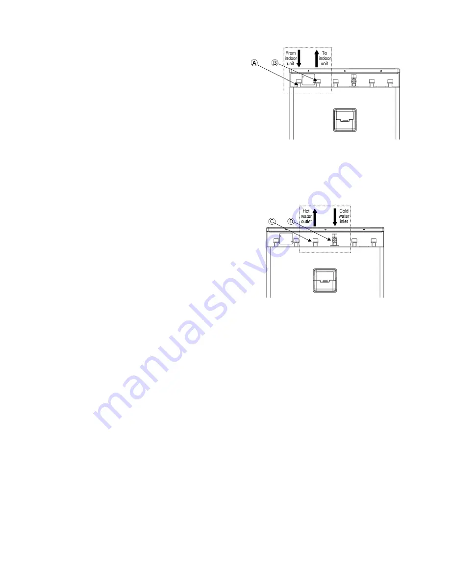
Tank Unit To Indoor Unit /Heat Exchanger Unit Piping Installation
This Tank Unit is designed for combination with Panasonic
Air-to-Water Heatpump System (indoor unit and outdoor
unit). If another manufacturer’s indoor unit and outdoor unit
are being used in combination with Panasonic Tank Unit,
neither optimum operation nor reliability of the system is not
guaranteed. Thus warranty cannot be given in such case.
• Connect Tank Unit tube connector
A
(indicated with
“INDOOR UNIT (IN)”) to water outlet connector of indoor
unit.
• Connect Tank Unit tube connector
B
(indicated with
“INDOOR UNIT (OUT)”) to water inlet connector of indoor
unit.
• Do not install any valves between unit and water piping to
avoid accidental closure of water supply to the unit.
• Failure to connect the tubes appropriately might cause the
unit malfunction.
2
Cold Water Supply And Hot Water Supply Piping Installation
• In high water pressure or water supply is above 500kPa,
please install the regulator valve for water supply. If the
pressure higher than that, it might damage the Tank Unit.
• A Pressure Reducing Valve (purchased separately) with
below specification is strongly advised to be installed at the
cold water inlet
D
(indicate with “COLD WATER (IN)”) of
Tank Unit. Refer Typical piping installation section to locate
the Pressure Reducing Valve.
Recommended Pressure Reducing Valve specifications:
- Maximum outlet pressure: 0.3 Mpa (3 bars)
- Operating temperature range: Min. 1
q
C – Max. 70
q
C
- Sized to meet application and local code condition.
• Install an expansion vessel (purchase separately) on cold
urban water line if pressure reducing valve is used.
• Must connect a faucet to Tank Unit hot water outlet
C
(indicated with “HOT WATER (OUT)”) and urban water
supply, in order to supply water with appropriate temperature
for shower or tap usage. Failure to do so might cause
scalding.
• Failure to connect the tube appropriately might causing the
Tank Unit malfunction.
Содержание WH-TX30B9E8
Страница 7: ...7 4 Location of Controls and Components 4 1 Tank Unit 4 1 1 Location of Control ...
Страница 8: ...8 4 1 2 Main Components ...
Страница 9: ...9 5 Dimensions ...
Страница 10: ...10 6 Water Cycle Diagram ...
Страница 11: ...11 7 Wiring Connection Diagram ...
Страница 12: ...12 8 Electronic Circuit Diagram 8 1 Indoor Unit ...
Страница 13: ...13 9 Printed Circuit Board 9 1 Tank Unit 9 1 1 Main Printed Circuit Board ...
Страница 14: ...14 9 1 2 Surge Printed Circuit Board ...
Страница 47: ...47 15 2 Heater Removal Procedures ...
Страница 48: ...48 15 3 Main Printed Board Removal Procedures ...
Страница 49: ...49 15 4 Control Board Removal Procedure ...
Страница 50: ...50 15 5 Pressure Relief Valve Procedures ...
Страница 51: ...51 15 6 Flow Switch Removal Procedures 15 7 Water Pump Removal Procedures ...
Страница 52: ...52 16 Technical Data 16 1 Pump Characteristic 16 2 Water Tank Sensor Characteristic ...
Страница 53: ...53 ...
Страница 54: ...54 ...


