background image

E-5

TABLE OF CONTENTS

INTRODUCTION

Precautions .................................................... 6

Daily maintenance and regular inspection ..... 7

Precautions on the use of cleaning tape ........ 8

Cassette tape ................................................. 8

Condensation ................................................. 9

NAMES AND FUNCTIONS OF VARIOUS PARTS

Front panel ................................................... 10

Rear panel .................................................... 14

Wireless remote controller ........................... 16

ON-SCREEN DISPLAY

Regarding on-screen display ........................ 18

Status display ............................................... 19

Event display ................................................ 21

Alarm display ................................................ 22

PREPARATION

Provided wireless remote controller ............. 24

Power ........................................................... 26

Selecting the NTSC/PAL signal system ....... 28

Loading/ejecting cassettes ........................... 29

Setting/displaying date and time .................. 30

RECORDING

Connection and setting ................................ 33

Setting time codes ........................................ 35

Recording method ........................................ 37

Series recording function ............................. 38

Audio dubbing .............................................. 39

PLAYBACK

Connection/setting ....................................... 41

Basic playback method ................................ 43

Special playback function ............................. 44

Locate function ............................................. 46

Selecting playback audio output ................... 47

EDIT

Using the unit in an editing system .............. 48

MENU SCREEN

Structure of the menu ................................... 51

Setting the menu .......................................... 52

Contents of the menus ................................. 54

OTHERS

Placing the unit in an upright position .......... 61

Warning display ............................................ 62

Troubleshooting ............................................ 64

Checking the hour meter .............................. 65

Specification ................................................. 66

Содержание VQT0C55

Страница 1: ...future use LLT0030 001A Printed in Thailand VQT0C55 Model AG E Digital Video Cassette Recorder PAL English Italiano Español Français Deutsch EJECT MENU REW SET FF PLAY STOP REC INH PAL AUDIO NTSC DVCAM PAUSE POWER REC A DUB CH 1 3 2 4 LINE DV S VIDEO OFF 9PIN WIRELESS INPUT REMOTE MIC AG DV2500 ...

Страница 2: ...ters REMOTE TWIST PAIR CABLE 5 meters SAFETY PRECAUTIONS Attention Attentie Batteries are used for memory back up in the product and remote controller At the end of their useful life you should not throw them away Instead hand them in as small chemical waste Baterrijen zijn gebruik gemaak voor inladen van geheugen voor allerlei producten onder ander afstandbediening Wanneer de batterij niet meer b...

Страница 3: ...ed from your local Panasonic Dealer IF THE FITTED MOULDED PLUG IS UNSUITABLE FOR THE SOCKET OUTLET IN YOUR HOME THEN THE FUSE SHOULD BE REMOVED AND THE PLUG CUT OFF AND DISPOSED OF SAFELY THERE IS A DANGER OF SEVERE ELECTRICAL SHOCK IF THE CUT OFF PLUG IS INSERTED INTO ANY 13 AMP SOCKET If a new plug is to be fitted please observe the wiring code as shown below If in any doubt please consult a qua...

Страница 4: ...for this VTR Equipped with composite and S VIDEO in put output terminal devices Equipped with DV IN OUT terminals IEEE1394 It can exchange digital signals with IEEE1394 compatible devices Dual support for NTSC PAL It automatically determines the signal system when playing back or receiving DV signal input It supports composite or Y C signal input with the use of a switch Wireless remote control It...

Страница 5: ...electing the NTSC PAL signal system 28 Loading ejecting cassettes 29 Setting displaying date and time 30 RECORDING Connection and setting 33 Setting time codes 35 Recording method 37 Series recording function 38 Audio dubbing 39 PLAYBACK Connection setting 41 Basic playback method 43 Special playback function 44 Locate function 46 Selecting playback audio output 47 EDIT Using the unit in an editin...

Страница 6: ...loading the cassette to prevent injury Place this VTR out of reach of young children As injury may result from fingers getting clamped when loading the cassette please keep this VTR out of reach of young children Please do not block the ventilation openings Avoid violent shocks to the unit Do not drop the unit Please remove the cassette tape from the cassette slot when transporting the unit Please...

Страница 7: ...placement if necessary 䢇 Replacement Maintenance necessity and fre quency depends on the environ ment and usage The above infor mation serves only as a guide Usage Time You can check the drum usage time via the hour meter display For details please refer to page 65 Checking the hour meter Maintenance consultation For details on the maintenance plan and fee please consult with your nearest PANASONI...

Страница 8: ...e The contents may be slightly dif ferent from those stated here Please follow the instructions in this manual Cassette tape This unit can record onto and playback standard DV and mini DV cassette tapes for SP mode only Please use the following PANASONIC cassettes with the or the logos 䡵 Erasure prevention DV cassettes have a safety slide at the back to prevent accidental erasure To prevent accide...

Страница 9: ...take out the cas sette Then place the AG DV2500E in a plastic bag and seal it before transporting the unit Leave the AG DV2500E in the sealed plastic bag until the unit has the same temperature as the surroundings This will prevent condensation CONDENSATION ON DRUM 䡵 For recording and storing videotapes in the best condition Observe the following instructions for the best recording and storage of ...

Страница 10: ...move the AC adapter to reduce energy consumption 2 Cassette slot Load a cassette into or unload it from the slot Please insert a standard DV or a mini DV cas sette Page 29 When the unit is in the POWER OFF state and if a cassette is loaded it goes into the ON state 3 A DUB Audio dubbing button LED Press this button for audio dubbing after re cording For audio dubbing set the AUDIO MODE item of the...

Страница 11: ...n the unit you wish to render operable can be se lected from the LOCAL FUNCTION item of the REMOTE menu Page 56 Control via the DV IN OUT terminal is pos sible ie unaffected by the switch setting 6 MIC Microphone input terminal This is the mini jack for monaural microphone input When this terminal is connected to a mi crophone sound input via the AUDIO IN termi nal located on the rear panel is not...

Страница 12: ...the A DUB button in the STILL mode the Au dio Dubbing Pause mode will be engaged When the menu is displayed use this button to confirm the menu items or setting values FF Fast forward button LED When the unit is in the STOP mode press this button to execute fast forward winding of the tape When the unit is in the PLAYBACK or STILL mode press this button to execute fast for ward playback During fas...

Страница 13: ...e and the 2 NTSC PAL switch located at the rear panel is set as PAL A tape recorded with PAL signals is played back When PAL system DV signals are in put while the INPUT switch is set at DV REC INH The LED lights up red in the following cases When a cassette with its rear switch set at the SAVE position is inserted When A DUB is not possible such as on tapes recorded in 48kHz mode Approx 3 sec Aud...

Страница 14: ...el lights up PAL Use this setting for PAL signal input The PAL indicator on the front panel lights up Memo For playback or DV signal input signals are determined automatically and not affected by the status of this switch Please turn the unit to POWER OFF before using this switch If switching is performed when the VTR is in the POWER ON mode the VTR will automatically go into the OFF mode before e...

Страница 15: ...ch on the front panel to DV Signals from this terminal are output regard less of the INPUT switch setting 5 S VIDEO IN S VIDEO input terminal 4P This is the input terminal for YC separate video sig nals To input video signals from this terminal set the INPUT switch on the front panel to S VIDEO When Wide discriminating signals are input ID signals for Wide discriminating signals are re corded 6 VI...

Страница 16: ...se quence Field image 1st 2nd alternate still 1st field image 2nd field image frame image 5 BLANK button When the unit enters the STOP mode press this button to begin a blank search Once it finds a blank part of the tape it will enter the STILL mode Page 46 6 AUDIO MUTING button During playback press this button to mute the audio output Press this button again to re en able audio output 7 AUDIO OU...

Страница 17: ...sume recording from the PAUSE mode REC button Hold down this button and press the PLAY button to begin recording During recording press this button to record an index on the tape when the INDEX WRITE item of the SYSTEM menu is set to ON When the unit enters the STOP mode hold ing this button down will enable you to check the value of the time code generator F ADV button Each time this button is pr...

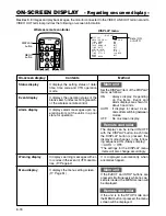
Страница 18: ...ess remote control It displays alarm messages upon op eration errors or if the unit is in a poor state for operation Main unit Set the DISPLAY item of the DISPLAY menu as follows ON Always display Depending on the items Event and Alarm displays are shown for about 3 seconds AUTO It displays for about 4 sec onds after switching between modes OFF No on screen display Remote controller The display ca...

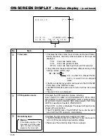
Страница 19: ...inal is displayed CH1 2 CH3 4 MIX only in 32K mode The AUDIO INFO item of the DISPLAY menu can be set to activate deactivate the display Memo If the time code display po sition is set to the upper left this item will be displayed on the lower right 2 Date time It displays the date D M Y and time HR MM SS When the unit is in the RECORDING or STOP mode it dis plays the data of the built in clock Dur...

Страница 20: ...played 4 VTR operation mode It displays the VTR operation modes including PLAY EJECT FF REW STOP STANDBY OFF STILL REC REC PAUSE A DUB A DUB PAUSE SHTL shuttle search JOG F ADV R ADV BLANK SRH blank search NO CAS SETTE cassette not loaded POWER OFF When SHTL or JOG is displayed the speed will also be dis played at the same time The VTR MODE item of the DISPLAY menu can be set to turn on off the VT...

Страница 21: ...es the index search position When an index is written on the tape during recording 䡵 Display at position B Display for about 3 seconds Display Contents Audio is muted with the re mote controller Audio is de muted with the remote controller The standard level of the playback or EE audio level is set to NORMAL or ATT with the remote controller Theplaybackaudiochannelis set to CH1 2 CH3 4 or MIX with...

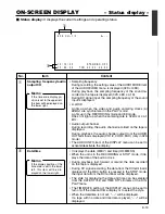
Страница 22: ...y goes off Displayed irrespective of the DISPLAY mode setting Despite DV connection signals are not received Displayed when DISPLAY mode is set to ON AUTO 3 2 K CH 1 2 0 m i n H E A D C L E A N I NG R EQU I R E D I N V A L I D T A P E 1 0 1 0 0 2 S T A ND B Y O F F 1 2 0 0 0 0 T CR 0 2 0 0 0 0 0 0 A B 䡵 Display at position A Displays which show the state of the unit continues to be displayed here ...

Страница 23: ...AUDIO VIDEO menu is set to 48K The tape is recorded with a sample frequency of 48kHz The user attempts to perform audio dubbing on a tape recorded in the LP mode The user attempts to perform audio dubbing on a blank tape The user attempts to perform audio dubbing during DV signal input The INPUT switch is set to DV This message is displayed when the signal system is changed during audio dubbing NT...

Страница 24: ...ease use 2 new batteries Do not mix new and old batteries Please load the batteries correctly accord ing to the ª and signs Please read the precautions printed on the batteries Precautions on the use of battery The provided batteries are for confirmation of operation If the remote controller is not to be used for a long period of time please remove the batteries from the compartment If the remote ...

Страница 25: ... WIRELESS INPUT REMOTE MIC AG DV2500 Sensor for the wireless remote controller About 30 About 30 Not further than 6m Notes The remote controller will hardly work if there are obstructive objects between the remote control sensor of the main unit and the remote controller The remote controller will hardly work when sunlight or strong light shines directly on the remote control sensor of the main un...

Страница 26: ...d mains cable to the AC IN terminal of the AC adapter 4 Connect the mains cable to the power socket Power is channeled into the unit and the POWER indicator lights up red POWER OFF mode If the DC IN MODE item of the SYSTEM menu is set to POWER ON or PLAY the POWER indicator will light up green POWER ON mode If it is set to PLAY the VTR will automatically start to play the loaded tape Memo Even in ...

Страница 27: ...nplug the AC adapter To disconnect the AC adapter please unplug the mains cable from the socket first 䡵 When the unit is in the POWER OFF mode the POWER indicator lights up red press the POWER button on the unit or the remote controller The power is turned on and the POWER indi cator lights up green The unit is now ready for operation POWER ON mode Memo Once a cassette has been loaded in the POWER...

Страница 28: ...e tape is automatically identified regardless of the NTSC PAL switch setting During DV signal input the signal system of the input signal is automatically identified regardless of the NTSC PAL switch setting This unit is equipped with a function to automatically detect the signal system of the cassette being played back or the signal being received at the DV input connector However this function m...

Страница 29: ...ndicator blinks The indicator lights up when cassette loading is complete EJECT MENU REW SET FF PLAY STOP REC INH PAL AUDIO NTSC DVCAM PAUSE POWER REC A DUB CH 1 3 2 4 LINE DV S VIDEO OFF 9PIN WIRELESS INPUT REMOTE MIC AG DV2500 EJECT MENU REW SET FF PLAY STOP REC INH PAL AUDIO NTSC DVCAM PAUSE POWER REC A DUB CH 1 3 2 4 LINE DV S VIDEO OFF 9PIN WIRELESS INPUT REMOTE MIC AG DV2500 Standard DV cass...

Страница 30: ...0 0 0 0 0 H E X I T C L OC K A D J U S T D A T E D M Y 1 0 1 0 0 2 T I ME 0 0 0 0 P AGE B A C K Top MENU CLOCK ADJUST menu Setting the date and time The date and time data is set up via the CLOCK ADJUST menu Setting can be performed while viewing the monitor screen connected to the VIDEO LINE OUT or S VIDEO OUT terminal The date and time can be set up using either the remote controller or the unit...

Страница 31: ...on Remote controller 1Press the 䊱 or 䊲 button and bring the cursor to the date or time setting Then press the 䊳 or SET button 2Press the 䊳 or 䊴 button and select the data seg ment to set up The selected data seg ment blinks 3Press the 䊱 or 䊲 to set the value 4Repeat step 1 3 After completing the necessary settings press the SET button Memo The seconds segment cannot be set up After the minute segm...

Страница 32: ...SPLAY BARS MENU SEARCH BLANK STILL MODE VCR POWER I AUDIO MUTING DISPLAY button Top MENU DISPLAY menu Setting 1 Select DISPLAY SET item from the top MENU and dis play the DISPLAY menu 2 Set the TIME DATE setting on the DISPLAY menu 䡵 TIME DATE OFF Does not display date or time TIME Displays time only DATE Displays date only DATE TM Displays both the time and date 3 Set the DATE STYLE and TIME STYL...

Страница 33: ...that of the player The Date and time data from the DV terminal will be recorded To record the time code data from the DV terminal set the DV TC DUP item of the TIME CODE menu to ON Page 58 RECORDING Connection and setting This chapter explains the connection setting and operation methods required to use this unit as a recorder This unit cannot be used as an editing system recorder Connection 䡵 Whe...

Страница 34: ...ront lights up depending on the setting Before setting the NTSC PAL switch please set the unit to the POWER OFF mode 䡵 Selecting the video input signal Please use the INPUT switch on the front panel S VIDEO Input Y C separate video signals LINE Input composite video signals DV Input DV signals 䡵 Setting the AUDIO VIDEO menu Page 57 AUDIO MODE Use this menu item to set the audio sampling frequency ...

Страница 35: ...TOP REC INH PAL AUDIO NTSC DVCAM PAUSE REC UB CH 1 3 2 4 NE S VIDEO PUT PLAY button EJECT button PAUSE button FF button STOP button REW button DISPLAY BARS MENU SEARCH SEARCH SET BLANK STILL MODE VCR POWER I AUDIO MUTING OUT SEL OUT LEV MENU button button button button button SET button Memo When the REC button is held down in the STOP mode the value of the built in time code generator is displaye...

Страница 36: ... REW but ton to shift to the next digit segment 3Press the PLAY STOP but ton to change the value of the blinking digits 4Repeat 2 and 3 steps above and set all the values Press the PAUSE button Remote controller 1Select theTC item with the 䊱 䊲 button and press the SET or 䊳 button The hour digits blink 2Press the 䊳 䊴 button to shift to the next digit seg ment 3Press the 䊱 䊲 button to change the val...

Страница 37: ...ton 4 Resume recording Press the PAUSE button or press the PLAY button while holding down the REC button 5 Stop recording Press the STOP button When the INDEX WRITE item of the SYSTEM menu is set as ON an index signal is recorded at the starting position of re cording In the PLAYBACK mode the position where the index signal is recorded can be detected Index search 䡵 During recording please press t...

Страница 38: ...cords the data of the built in time code gen erator or the built in clock If the time code of the DV camcorder stops advancing with the DV TC DUP menu item set to ON the time code of this unit while per forming series recording also stops advanc ing Operation 1 Recording begins on the source unit Please record from the beginning of the re cording tape After inserting the tape wait 10 seconds be fo...

Страница 39: ...UB CH 1 3 2 4 LINE DV S VIDEO OFF 9PIN WIRELESS INPUT REMOTE MIC AG DV2500 PAUSE button STOP button INPUT switch PLAY button A DUB button MIC terminal For tapes recorded in the 32kHz audio mode audio dubbing can be performed on the CH3 and CH4 channel after the recording After recording Notes For tapes recorded in the 48kHz audio mode audio dubbing cannot be performed Audio dubbing cannot be perfo...

Страница 40: ... is played During audio dubbing noise may be produced on the playback video or playback sound but the recording is normal The playback sound of CH1 2 cannot be recorded on CH3 4 sound on sound During backspace operation of audio dubbing audio dubbing cannot be performed on unre corded parts When audio dubbing is performed on tapes re corded on other devices it may not record cor rectly Please reco...

Страница 41: ... 3 CH 2 4 LINE S VIDEO N I O U T 9PIN REMOTE AUX NTSC PAL DC 12V WARNING SHOCK HAZARD DO NOT OPEN AVIS RISQUE DE CHOC ELECTRIQUE NE PAS OUVRIR DV terminal DV terminal Player the rear panel of the main unit Monitor DV cable available separately Another VTR 䡵 Connecting this unit to a video device with no DV terminal analogue signal DV IN OUT AUDIO VIDEO CH 1 3 CH 2 4 LINE S VIDEO N I O U T 9PIN REM...

Страница 42: ...UP NTSC only Use this setting to determine whether to apply the setups to the composite video or Y C separate video output signals REC PAL AUDIO NTSC DVCAM POWER A DUB CH 1 3 2 4 LINE DV S VIDEO OFF 9PIN WIRELESS INPUT REMOTE MIC AG DV2500 REMOTE switch S Y S T EM S T I L L MOD E F I E L D S E R I E S R E C T I ME O F F S T I L L T I ME R 5 M I N P A U S E P RO T E C T F A D V I ND E X WR I T E ON...

Страница 43: ...dicator will light up 3 Pause Press the PAUSE button A still image is output Memo When output of still im age continues for a pro longed period the unit will automatically go into the tape protection mode The lapse time can be selected from the STILL TIMER item of the SYS TEM menu Remote controller Press the STILL MODE button The still image changes as follows each time the button is pressed 4 Res...

Страница 44: ...eld by field 1st 2nd alternate 1st FIELD Image is advanced frame by frame and the 1st field image is displayed 2nd FIELD Image is advanced frame by frame and 2nd field im age is displayed FRAME Image is advanced frame by frame and frame image is displayed Operation 1 Set the unit to the STILL mode 2 Frame advance in the forward direction Press the F ADV button When the F ADV button is held down th...

Страница 45: ...frame advance 䡵 During the STILL mode If the SEARCH 䊱 buttons are pressed the tape will play in the forward direction If the SEARCH 䊲 buttons are pressed the tape will play in the reverse direction Changing the direction of playback 䡵 To change from normal or fast forward playback to re verse playback Press the p 䊴 button If this button is pressed during playback reverse playback will be engaged 䡵...

Страница 46: ...ton INDEX button INDEX 1 During index search this message is displayed on the monitor the number represents the position of the index Monitor screen Memo If the interval between index signals is less than 1 minute the function may not work well The specifications for index signal recording varies with the device used Blank search This function locates the unrecorded parts of the tape Use the remot...

Страница 47: ...io output press the button again 䡵 Selecting the audio output channel for playback of tapes recorded in the 32kHz mode Each time the OUT SEL button is pressed the channel changes in the following sequence CH3 CH4 CH3 audio is output via the CH1 3 AUDIO OUT terminal whereas CH4 audio is output via the CH2 4 AUDIO OUT terminal MIX Sounds mixed from CH1 and CH3 are output via the CH1 3 AUDIO OUT term...

Страница 48: ...E DE CHOC ELECTRIQUE NE PAS OUVRIR S VIDEO IN REF IN THROUGH OUT VIDEO LINE OUT 9PIN Remote controller AG A850 9PIN S VIDEO OUT Video Audio Player AG DV2500E Recorder AJ D455 Memo If editing precision is critical please input the composite signals of the VIDEO LINE OUT of AG DV2500E as standard synchronization sig nals into the editing remote controller Use the S VIDEO OUT terminal for video signa...

Страница 49: ...or AG A850 set this to TYPE 3 R EMO T E L OC A L F UNC T I ON S T P E J T P R E RO L L 7 S E C R E M F F R EW M O D E F F R E W R E M S T O P S E L E E P L A Y D E L A Y O F S Y N C H R O N I Z A T I O N O N C O N T R O L L E R S E L T Y P E 3 P A G E B A C K REMOTE menu Memo LOCAL FUNCTION For controlling with the REMOTE terminal use this menu item to select the buttons on the unit to be rendered...

Страница 50: ... panel to DV Connecting using DV 1394 terminal DV IN OUT AUDIO VIDEO CH 1 3 CH 2 4 LINE S VIDEO N I O U T 9PIN REMOTE AUX NTSC PAL DC 12V WARNING SHOCK HAZARD DO NOT OPEN AVIS RISQUE DE CHOC ELECTRIQUE NE PAS OUVRIR DV Terminal DV1394 Image Sound Control Non Linear Editing System EJECT MENU REW SET FF PLAY STOP REC INH PAL AUDIO NTSC DVCAM PAUSE POWER REC A DUB CH 1 3 2 4 LINE DV S VIDEO OFF 9PIN ...

Страница 51: ...T I ON S T P E J T P R E RO L L 7 S E C R E M F F R EW MOD E F F R EW R EM S T OP S E L E E P L A Y D E L A Y O F S Y NCHRON I Z A T I ON ON CON T RO L L E R S E L T Y P E 3 P AGE B A C K T I ME COD E T C 0 0 0 0 0 0 0 0 C L E A R C A NC E L ND F D F N T S C DROP D V T C DU P O F F T C OU T O F F S E T O F F P AGE B A C K D I S P L A Y D I S P L A Y ON COUN T E R POS I L OWE R R T I ME COD E ON V ...

Страница 52: ...MENU button ME NU S Y S T EM R EMO T E A UD I O V I D EO T I ME COD E D I S P L A Y S E T C L OC K A D J U S T F A C T OR Y S E T T I NG C A NC E L DRUM HOUR ME T E R 0 0 0 0 0 0 H E X I T Cursor S Y S T EM S T I L L MOD E F I E L D S E R I E S R E C T I ME O F F S T I L L T I ME R 5 M I N P A U S E P RO T E C T F A D V I ND E X WR I T E ON DC I N MOD E POWE R O F F P AGE B A C K Top MENU SYSTEM m...

Страница 53: ... 1Press the PLAY STOP but ton and bring the cursor to the item to be set 2Press the PAUSE or FF but ton 3Press the PLAY STOP but ton to change the value as desired 4Press the PAUSE button to confirm the value Remote controller 1Press the button and bring the cursor to the item to be set 2Press the SET or button 3Press the button to change the value as de sired 4Press the SET button to confirm the ...

Страница 54: ...isplays the menus related to the audio and video Displays the menu for setting time codes Displays the menu related to the displays on the monitor connected to the VIDEO LINE OUT or S VIDEO OUT terminal Displays the menu for setting date time For information on the setting method please refer to page 30 Setting date time Sets whether to return the values on the menu to those initially set at manuf...

Страница 55: ...ing time of the source tape is 180 mins 265MIN Use this setting if the recording time of the source tape is 270 mins Page 38 Series recording function Sets the interval after the lapse of which the tape protection mode will be engaged during an extended STILL mode The setting for the STILL mode can be done via the PAUSE PROTECT menu item 30SEC 30 seconds 1MIN 1 minute 3MIN 3 minutes 2MIN 2 minutes...

Страница 56: ...te when a com mand is received Use this setting if the locate cue up function does not work well Use this menu item to set the action to be performed when a STANDBY ON command is received via the 9 PIN REMOTE terminal or DV termi nal EE Sets the unit to the EE mode The unit will go into the STOP mode PB Sets the unit to the PLAY mode The unit will go into the STILL mode Use this menu item to adjus...

Страница 57: ...ut ATT Attenuates the output level to about 8dB Use this setting when playing tapes recorded on aVTR of which the stand ard level for PCM audio is full scale 12dB The playback level is decreased by 8dB NORM Usually this is selected Memo This setting can also be selected with the AUDIO OUT LEV button on the wireless remote controller During recording OFF Select this when analogue signals are input ...

Страница 58: ...DROP Sets the unit to the drop frame mode Use this set ting for real time based time codes Use this menu item to select the type of time code to be recorded for DV signal input OFF Records the time codes of the built in time code generator of the main unit ON Records the time codes and user bits input to the DV IN terminal The time code framing mode automatically takes on that of the input time co...

Страница 59: ...ed from the DISPLAY button of the wireless remote controller Use this menu item to select the position on the monitor for time code display LOWER R Lower right LOWER L Lower left UPPER R Upper right UPPER L Upper left CENTER Centre Use this menu item to turn on off the display of time codes on the monitor OFF No display ON Display Use this menu item to turn on off the display of the VTR mode on th...

Страница 60: ... D Y Display month day year D M Y Display day month year Select the time format 24HOUR Display in the 24 hour mode 12HOUR Display in the 12 hour mode Use this menu item to choose whether to output as test signals colour bar signals from the built in signal generator OFF No output ON Output Memo This colour bar cannot be used as the standard signal for hue calibration This setting can also be selec...

Страница 61: ...Notes To place the VTR in an upright position please use the provided stand If the stand is not used the unit may topple and result in injuries or breakdown Please place the unit on a leveled place When inserting the cassette do not remove your hand until the cassette is being drawn into the unit Particularly when a mini DV cassette is used removing your hand too early may cause the cassette to dr...

Страница 62: ...ss of the DISPLAY mode Display Status Action LOW VOLTAGE HEAD CLEANING REQUIRED The DC power voltage is low The unit will eventually go into the POWER OFF mode if operation is continued The video head is dirty If the head is clogged it will be detected and the alarm message will be displayed during the PLAYBACK mode When the STOP mode is engaged or when the cas sette is ejected the display will go...

Страница 63: ...nit blinks in green The unit will not accept any operation commands Please leave the power on and wait for the display to disappear This error can be resolved by restarting the unit However doing so may damage the tape in some cases Please consult your PANASONIC authorized dealer Press the EJECT button and retrieve the cassette Then replace the tape This error can be resolved by restarting the uni...

Страница 64: ...cassette first Push the centre of the cassette and make sure that the cassette enters levelly Is the slide of the cassette set to REC Please set it to REC if it is at the SAVE position Is the front REMOTE SWITCH set at OFF If it is set at 9 PIN or WIRELESS main unit operation is not possible Is the front REMOTE switch set at 9PIN Is the tape damaged Please replace the cassette Is the head dirty Pl...

Страница 65: ... SEL OUT LEV REC F ADV MENU button ME NU S Y S T EM R EMO T E A UD I O V I D EO T I ME COD E D I S P L A Y S E T C L OC K A D J U S T F A C T OR Y S E T T I NG C A NC E L DRUM HOUR ME T E R 0 0 0 2 0 0 H E X I T Top MENU To set the unit to the STOP mode When operating with the buttons on the main unit unload the cas sette 1 Display the top MENU Main unit Press the EJECT and STOP buttons simultaneo...

Страница 66: ...ecording format 8 bit 13 5MHz 4 1 1 NTSC 4 2 0 PAL Video input Line composite 1 0V p p 75Ø unbalance S VIDEO Y 1 0V p p 75Ø unbalance C 0 286V p p NTSC 0 3V p p PAL 75Ø unbalance Video output Line composite 1 0V p p 75Ø unbalance S VIDEO Y 1 0V p p 75Ø unbalance C 0 286V p p NTSC 0 3V p p PAL 75Ø unbalance Audio Recording format 16 bit 48kHz 2 channels PCM audio 12 bit 32kHz 4 channel PCM audio Nu...

Страница 67: ...7 Diagram of external dimension Unit mm 68 174 260 EJECT MENU REW SET FF PLAY STOP REC INH PAL AUDIO NTSC DVCAM PAUSE POWER REC A DUB CH 1 3 2 4 LINE DV S VIDEO OFF 9PIN WIRELESS INPUT REMOTE MIC AG DV2500 ...

Страница 68: ......
Отзывы: