background image

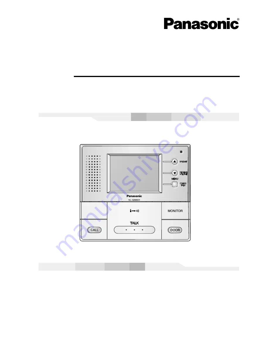
Sub Monitor Station


Installation and Operation Guide

Model No.


VL-GM001A

Thank you for purchasing a Panasonic Sub Monitor Station.

Please read this Installation and Operation Guide before using the unit and
save for future reference.

Video Intercom System

Содержание VL-GM001

Страница 1: ...llation and Operation Guide Model No VL GM001A Thank you for purchasing a Panasonic Sub Monitor Station Please read this Installation and Operation Guide before using the unit and save for future reference Video Intercom System ...

Страница 2: ...guarantee that interference will not occur in a particular installation If this equipment does cause harmful interference to radio or television reception which can be determined by turning the equipment off and on the user is encouraged to try to correct the interference by one or more of the following measures Reorient or relocate the receiving antenna Increase the separation between the equipme...

Страница 3: ...ocked by placing the product on a bed sofa rug or other similar surface 8 Do not install near any heat sources such as radiators heat registers stoves or other apparatus including amplifiers that produce heat This product should not be placed in a built in installation such as a bookcase or rack unless proper ventilation is provided or the manufacturer s instructions have been adhered to 9 Do not ...

Страница 4: ... Do not make any wiring connections when the power supply is turned on 12 Never install wiring during a lightning storm 13 Do not connect a power cable other than the specified voltage 14 Do not connect the power cable to any terminal other than the one specified 15 When existing chime wires are used it is possible that they contain AC voltage Electric shock or unit damage could result Contact an ...

Страница 5: ...t Information For best performance If a power failure occurs the unit will not function Do not place any object within 20 cm 8 inches of the sub monitor station This may cause communication errors or malfunction ...

Страница 6: ...Power cable 1 Enclosed in the AC adaptor case Wood screws 2 For the AC adaptor case 4 mm x 16 mm 3 16 x 5 8 Introduction and Installation Sub Monitor Station A Sub Monitor Station is an optional unit which when used through the Monitor Station operates just like the Monitor Station Up to two of these units can be connected to the system Quantity ...

Страница 7: ...EIVE VOLUME button MENU button PRESS TALK button MONITOR button Allows you to monitor the sound and camera image from the door station DOOR button Allows you to open the door TALK button To answer a door call and or speak to the visitor CALL button To call another monitor unit Speaker Ventilation holes are located at the bottom Do not cover these Introduction and Installation ...

Страница 8: ...or station into a wall Refer to the Installation and Operation Guide that is included with the flush mount unit for details on installing the flush mount unit Standard installation position of the sub monitor station Place the sub monitor station in a location so that your eyes are the same height as the center of the display Note In areas surrounded by high electrical field disturbance may occur ...

Страница 9: ...nnect to terminals H21 and H22 of the sub monitor station NOTE This chime wiring schematic diagram is only an example Refer to the wiring instruction provided with your chime for detail Refer to the technical data on page 18 when connecting to a chime All connections are non polar Connect to terminals H11 and H12 of the monitor station Introduction and Installation Wiring schematic diagram All mon...

Страница 10: ...material from between the front case and the bottom case The front case and the bottom case are not joined together so be careful not to drop them when taking them out of the box Bottom case Front case Padding material Connector 2 Remove the terminal cover Bottom case Terminal cover Introduction and Installation ...

Страница 11: ...11 3 Install the bottom case to a wall using the wood screws 4 mm x 35 mm 3 16 x 13 8 Before drilling see page 8 for installation location Installation size Introduction and Installation ...

Страница 12: ...ematic diagram on page 9 4 Attach the power cable to the terminal See page 16 for details on how to attach the power cable If you want to use your own power cable see page 9 for the type and distance Inside of main unit bottom case Button Power switch When the front case is attached the power switch will be pressed and power will be supplied Terminal Non polar Wire Not included Introduction and In...

Страница 13: ...of front case forward to remove it Remove the connector screw and then remove the connector Do not pull the wire when removing the connector Introduction and Installation 6 Remove the sheet covering the connector Next after installing the terminal cover in the bottom case attach the connector by tightening the connector screw Next align the lower portion of the bottom case with the lower portion o...

Страница 14: ... attach the power cable see page 16 DC terminal AC adaptor Power cord To AC outlet Power cable 9 Attach the DC cord to the clamp on the rear of the DC terminal This will help to avoid the DC cord to disconnect from the DC terminal DC terminal DC cord Clamp 7 Take out the AC adaptor and the DC terminal from the case Push the arrow mark on the front case then release from the rear case Take out the ...

Страница 15: ...al beforehand See step 9 on page 14 for details Take out the cardboard and wood screws from the AC case beforehand Wood screws Case 83 5 mm 3 5 16 Wall 2 Pack the AC adaptor and DC terminal as shown Pack the AC adaptor in the rear case Be sure to run the power cord through the power cord hole Pack the DC cord in the rear case Be sure to bundle the DC cord so that it will not touch the bottom of th...

Страница 16: ...then release from the rear case To attach the power cable While pressing on the button hard with a pointed object such as a screwdriver insert the power cable into the terminal connector To disconnect the power cable press on the button hard while pulling out To attach an optional power cable cut off about 12 mm 1 2 of the cable cover then push in firmly until the end of the cable is securely inse...

Страница 17: ... soap benzine thinner wax petroleum or boiling water Also do not spray with insecticide glass cleaner or hair spray This could cause a change in color or quality Clean the unit with a soft dry cloth when cleaning For excessive dirt wipe the unit with a slightly damp cloth Cleaning Help ...

Страница 18: ...lush mount unit is required Flame retardant ABS resin panel acrylic resin Note Design and specifications are subject to change without notice The pictures and illustrations in these instructions may vary slightly from the actual product AC adaptor Part number PFAP1014 Power supply Output voltage Output current Dimensions Mass Weight Operating environment 100 V 240 V AC 50 Hz 60 Hz 24 V DC 2 A Appr...

Страница 19: ...19 ...

Страница 20: ...on of North America One Panasonic Way Secaucus New Jersey 07094 U S A Panasonic Puerto Rico Inc San Gabriel Industrial Park Ave 65 de Infantería Km 9 5 Carolina Puerto Rico 00985 U S A Copyright This material is copyrighted by Panasonic Communications Co Ltd and may be reproduced for internal use only All other reproduction in whole or in part is prohibited without the written consent of Panasonic...

Отзывы: