background image

21

Introduction and Installation

3

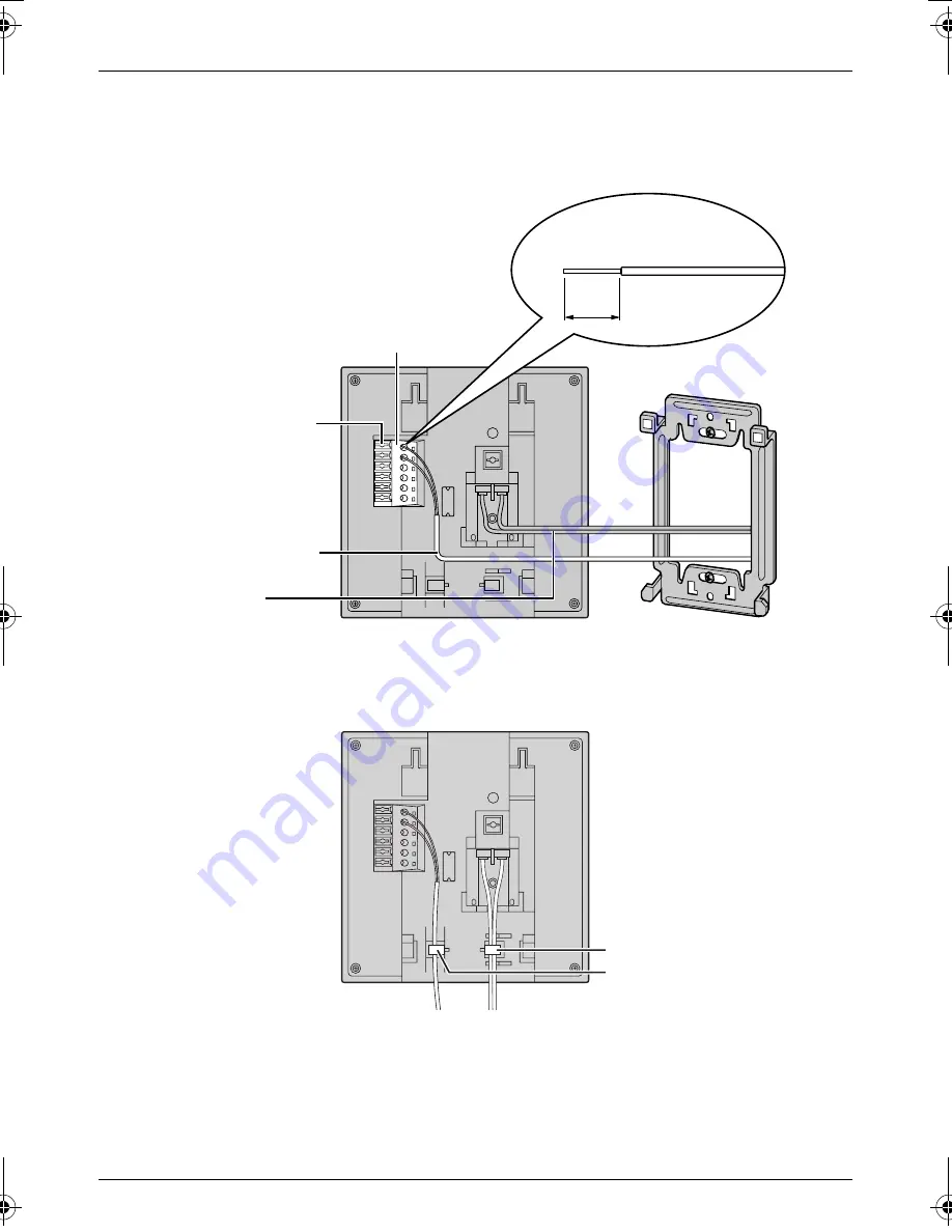
Attach the wires that connect to the door station to the terminal. See page 26 for details 
on how to attach the wires.

L

See page 15 for the wire type and distance.

L

See the wiring schematic diagram on page 15.

L

If you want to connect the wires and the power cable without them passing through a 
hole in the wall, connect by passing the wires through the wire guide, and the power 
cable through the power cable guide.

Button

Terminal
(Non polar)

Power cable

Wire (Not included)

Stripped end of the wire

9 mm

Power cable guide
Wire guide

G201CE(E).book  Page 21  Friday, November 11, 2005  4:46 PM

Содержание VL-G201

Страница 1: ...urchasing a Panasonic Video Intercom System Please read this Installation and Operation Guide before using the unit and save for future reference Video Intercom System Installation and Operation Guide Model No VL G201 ...

Страница 2: ...c PBXs 9 Location of controls 10 Before installation 13 Installing the door station 16 Installing the monitor station 20 Using with another machine 27 Using the Unit Turning PBX MODE switch ON OFF 28 Connecting to a PBX 30 Answering a door call 31 Monitoring the outside 34 Opening a door Door Opener 35 Help Troubleshooting 36 Cleaning 37 General Information Technical data about this product 38 ...

Страница 3: ... 8 Do not install near any heat sources such as radiators heat registers stoves or other apparatus including amplifiers that produce heat This product should not be placed in a built in installation such as a bookcase or rack unless proper ventilation is provided or the manufacturer s instructions have been adhered to 9 Do not defeat the safety purpose of the polarized or grounding type plug A pol...

Страница 4: ...rmally or has been dropped SAVE THESE INSTRUCTIONS Information on Disposal for Users of Waste Electrical Electronic Equipment private households This symbol on the products and or accompanying documents means that used electrical and electronic products should not be mixed with general household waste For proper treatment recovery and recycling please take these products to designated collection p...

Страница 5: ...tre when the following conditions occur A If smoke rises or an unaccustomed noise or smell is discharged from the unit B If metal objects have been dropped inside the monitor station 9 Do not put your ear s near the speaker as loud sounds emitted from the speaker may cause hearing impairment 10 Only a qualified technician is allowed to connect a power cable to the unit Contact an authorised servic...

Страница 6: ...D THE PLUG CUT OFF AND DISPOSED OF SAFELY THERE IS A DANGER OF SEVERE ELECTRICAL SHOCK IF THE CUT OFF PLUG IS INSERTED INTO ANY 13 AMP SOCKET If a new plug is to be fitted please observe the wiring code as shown below If in any doubt please consult a qualified electrician IMPORTANT The wires in this mains lead are coloured in accordance with the following code Blue Neutral Brown Live As the colour...

Страница 7: ...rs the unit will not function L Do not place any objects within 20 cm of the monitor station This may cause communication errors or malfunction L Do not install the unit in places where it will be affected by extremely high frequency radio waves near broadcasting antennas etc This may cause the display to flicker or an interrupting noise to occur FUSE 20 cm 20 cm 20 cm 20 cm ...

Страница 8: ...cket 1 Attached to rear of the monitor station 3 Wood screw 2 For the monitor station 4 mm x 16 mm 4 Power cable 1 5 Door station 1 6 Mounting bracket 1 Attached to rear of the door station 7 Wood screw 2 For the door station 3 8 mm x 20 mm 8 Allen key 1 9 Bolt cover 2 One for spare j AC adaptor 1 Enclosed in the AC adaptor case ...

Страница 9: ...TDA600E KX T206E KX TA624E KX TEA308E KX TES824E Compatibility of following Panasonic PBX is depending on software version Please consult your dealer KX TDA15E KX TDA30E KX TDA100E KX TDA200E For German users This unit is compatible with the following Panasonic PBXs 1 KX TDA600NE Compatibility of following Panasonic PBX is depending on software version Please consult your dealer KX TDA15NE KX TDA3...

Страница 10: ...n Location of controls Monitor station Front view Side view Rear view MONITOR BRIGHT DOOR TALK VOLUME RINGER VOLUME RINGER ANSWER AUTO PUSH HOLD HIGH LOW OFF ANSW ER AUTO PUSH HOLD HIG H LOW OFF B I D E F J G A H C OFF PBX MODE ON K ...

Страница 11: ...ls are available E DOOR button L Allows you to open the door page 35 F Speaker G TALK button L To answer a door call and or speak to the visitor page 31 H Talking indicator L Lights while you are talking I RINGER VOLUME switch L To adjust the ringer volume 3 levels high low off are available J ANSWER switch L To change the answering mode page 31 K PBX MODE switch L To connect the unit to a PBX tur...

Страница 12: ...display B Microphone C Call Button L The Call Button is lighted with a blue LED light while the power is on L When a visitor presses the Call Button a ringer tone will ring at the monitor station D Speaker E Water drain hole L This hole allows rain water to drain Do not cover it F Camera angle control lever L The camera angle can be adjusted when installing the door station page 13 17 A B E F C D ...

Страница 13: ...r noxious fumes occur Within 2 m of a TV microwave personal computer air conditioner or any other electrical device Standard installation position of the door station and camera range Upper lower range L Side view of when the camera is facing the front at 0 Left right range L Top view of when the camera is facing the front at 0 L Top view of when the camera is facing the left at 15 L Top view of w...

Страница 14: ...r station Where echoing occurs causing the unit to beep frequently L Make sure the back of the door station is not subject to water Standard installation position of the monitor station Place the monitor station in a location so that your eyes are the same height as the centre of the display Note L In areas surrounded by high electrical field disturbance may occur in the monitor station s image or...

Страница 15: ...r cable between the monitor station and the AC adaptor Type Ф1 2 Fire alarm cable 16 AWG Distance Maximum 30 m L Wire between the monitor station and the door station Type General cable CAT 3 24 AWG Distance Maximum 100 m Loop resistance 18 4 Ω or lower L Wire between the monitor station and PBX Type General cable CAT 3 24 AWG Distance Maximum 100 m D1 D2 Door station Monitor station AC adaptor Po...

Страница 16: ...or station there is a hole to allow water to drain Do not cover it up when installing 1 Unscrew the hex head screw using the longer end of the allen key and remove the mounting bracket from the rear of the door station L The pin hole camera is not a screw to be touched or removed Hex head screw Attached to the door station Allen key Mounting bracket Pin hole camera ...

Страница 17: ...the monitor station to the terminal connector by unscrewing the screws pushing in the wires then tightly fastening the screws L See page 15 for the wire type and distance L You can change the camera angle using the camera angle control lever See page 13 for details Wall Mounting bracket 83 5 mm Wire Not included Wood screws Camera angle control lever Wire Not included Terminal connector Non polar ...

Страница 18: ...o connect the wires without them passing through a hole in the wall connect the wires by passing them through the ribs and the wire hole 4 Mount the door station to the mounting bracket Push the door station down until it is secure Rib Wire hole 1 2 ...

Страница 19: ...hex head screw using the longer end of the allen key 6 Attach the bolt cover using the shorter end of the allen key L Use protrusion on the shorter end of the allen key to rotate the bolt cover until it is secure Hex head screw Allen key Allen key ...

Страница 20: ... the wood screws 4 mm x 16 mm L Remove the mounting bracket from the rear of the monitor station beforehand L Before drilling see page 13 for installation location 2 Attach the power cable to the terminal See page 26 for details on how to attach the power cable L If you want to use your own power cable see page 15 for the type and distance Wall Wire Not included Mounting bracket 83 5 mm Wood screw...

Страница 21: ...ype and distance L See the wiring schematic diagram on page 15 L If you want to connect the wires and the power cable without them passing through a hole in the wall connect by passing the wires through the wire guide and the power cable through the power cable guide Button Terminal Non polar Power cable Wire Not included Stripped end of the wire 9 mm Power cable guide Wire guide ...

Страница 22: ... it is secure 5 Take out the AC adaptor and the DC terminal from the case L Push the arrow mark on the front case then release from the rear case L Take out the cardboard and wood screws The wood screws are necessary when attaching the AC adaptor and the DC terminal to a wall page 24 1 2 AC adaptor DC terminal Arrow mark ...

Страница 23: ...Hz L Be sure to connect the power cable to the 2 holes on the left side of the DC terminal L For details on how to attach the power cable see page 26 7 Attach the DC cord to the clamp on the rear of the DC terminal L This will help to avoid the DC cord to disconnect from the DC terminal To AC outlet DC terminal Power cable AC adaptor Power cord 1 2 3 DC cord DC terminal Clamp ...

Страница 24: ...nd wood screws from the AC case beforehand 1 Attach the rear part of the case to a wall using the wood screws 4 mm x 16 mm 2 Pack the AC adaptor and DC terminal as shown 1 Pack the AC adaptor in the rear case LBe sure to run the power cord through the power cord hole 2 Pack the DC cord in the rear case LBe sure to bundle the DC cord so that it will not touch the bottom of the case 3 Pack the DC te...

Страница 25: ...25 Introduction and Installation 3 Attach the front of the case Note L To open the case again push the bottom of the front case then release from the rear case 1 2 ...

Страница 26: ...ush in firmly until the end of the cable is securely inserted into the power connection terminal 2 To attach the wires L Strip off of the wire cover so that about 9 mm of the wire is exposed L While pressing on the button with a pointed object such as a screwdriver insert the wire into the terminal connector L To disconnect a wire press on the button while pulling out Monitor station DC terminal 1...

Страница 27: ... turn off when the conversation has ended or when the conversation continued for more than about 3 minutes L If you answer a call from the door station with the monitor station the call will continue to ring at the extension for about 15 to 30 seconds If the extension user answers the call while the call is still ringing the door station user the monitor station user and the extension user can spe...

Страница 28: ...ge 30 turn PBX MODE switch on If not turn PBX MODE switch off The default setting is OFF 1 Remove the switch cover from the rear of the monitor station L Use a sharp thin object such as a mechanical pencil 2 Select ON or OFF default Switch cover OFF PBX MODE ON PBX MODE switch ...

Страница 29: ...29 Using the Unit 3 Attach the switch cover to the rear of the monitor station Switch cover ...

Страница 30: ...g or listening to the caller Note L If you answer a call from the door station with a PBX extension the camera image from the door station will be displayed at the monitor station If the monitor station user tries to answer the call a beep will sound The display will turn off when the conversation has ended or when the conversation continued for more than about 3 minutes L If you answer a call fro...

Страница 31: ...you can answer the call by voice page 32 PUSH mode default When a visitor calls you you can answer the call by pressing TALK You may then speak with the caller page 32 HOLD mode When a visitor calls you you can answer the call by pressing TALK Press TALK while speaking to the caller and release the button to allow the caller to speak to you page 32 Note L If the door station is located in a noisy ...

Страница 32: ...2 Speak to the visitor 3 To end the conversation press TALK Note L Make sure you are within about 50 cm of the monitor station L You can also answer the call by pressing TALK L Your initial reply should be brief less than 1 second otherwise AUTO mode will not start L If a visitor calls you a loud brief sound such as a barking dog may start AUTO mode even though you have not replied by voice HOLD m...

Страница 33: ...et L If you do not answer a door call within 30 seconds the display will turn off If you press TALK again the display will turn on again and you can talk to the visitor L The conversation will be automatically disconnected in about 1 minute and 30 seconds about 1 minute in HOLD mode To resume the conversation press TALK L At night or when there is not enough lighting in the doorway the display wil...

Страница 34: ...l be heard The inside sound will not be heard at the door station L If necessary press BRIGHT repeatedly to select the desired brightness 2 To end monitoring press MONITOR L Even if you do not press MONITOR monitoring will automatically end in about 1 minute Note L If the Call Button is pressed while you are monitoring the ringer tone will not be heard L To talk to the visitor while monitoring pre...

Страница 35: ...Unit Opening a door Door Opener You can open the door using the monitor station a separate Door Opener is required 1 While the display is on press and hold DOOR L The door will remain open while DOOR is pressed DOOR ...

Страница 36: ...nnel The ringer tone cannot be heard L The ringer volume is turned off Turn it on L The power cord is not connected Check the connections L Contact our service personnel I cannot talk to the visitor or the ringer tone rings regularly L Press and hold BRIGHT for about 10 seconds until a beep sounds Wait for another 10 seconds and try again L Contact our service personnel Sound cuts in out or fades ...

Страница 37: ...owder soap benzine thinner wax petroleum or boiling water Also do not spray with insecticide glass cleaner or hair spray This could cause a change in colour or quality The outside visitor complains the door station does not beep when the call button is pressed L PBX MODE switch is turned on although the unit is not connected to a PBX Turn off PBX MODE switch page 28 Problem Cause and solution ...

Страница 38: ...n Low active Less than 30 V AC 1 A 24 V DC 1 A Door station Power supply 1 Standby Approx 5 V DC 2 mA At operation Approx 20 V DC 180 mA Dimensions Approx height 165 mm x width 90 mm x depth 35 mm Mass Weight Approx 330 g Operating environment 10 C to 50 C Up to 90 RH Relative Humidity non condensing Installation method Wall mount Wall mount bracket included External material Aluminum 1 Supplied f...

Страница 39: ...39 General Information Note L Design and specifications are subject to change without notice L The pictures and illustrations in these instructions may vary slightly from the actual product ...

Страница 40: ...material is copyrighted by Panasonic Communications Co Ltd and may be reproduced for internal use only All other reproduction in whole or in part is prohibited without the written consent of Panasonic Communications Co Ltd 2005 Panasonic Communications Co Ltd All Rights Reserved Date of purchase Serial number found on the rear of the unit Dealer s name and address Dealer s telephone number ...

Отзывы: