20
3.3.5.
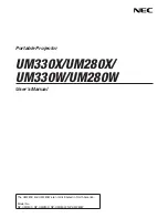
Installing Panaboard to the optional Stand
Note:
1. Use the washers included with the electronic board. Do
not use the washers included with Stand.
2. Do not tighten the screws too much. This may deform the
Stand.
3. By tightening the two screws with washers through holes
A and B, the unit will be positioned 100 mm (3 15/16")
higher than normal height (1,930 mm [6' 4"]).
1.
Attach the optional Stand to the unit.
• Each Stand has 3 holes (A, B, C).
1) Attach the Stand to the unit with the locking caster up.
2) When attaching the unit to the Stand at normal height (1,830
mm [6' 2/32"]), tighten the 2 screws (included in the Stand) with
washers using the hexagonal wrench through holes A and C.
2.
Stand the unit up.
3.
Attach the rivets (included in the Stand) to the holes in the Stand
that are not already in use.
• Normal height: 2 places
• Higher than normal height: 4 places
4.
Attach the clamp for the Power Cord to the upper side of the
Stand on the control box side.
Содержание UB-5838C
Страница 9: ...9 2 3 External View...
Страница 10: ...10 2 4 Control Panel Operation...
Страница 11: ...11 2 5 External Dimensions 2 5 1 UB 5838C...
Страница 12: ...12 2 5 2 UB 5338C...
Страница 101: ...101 13 Exploded View and Replacement Parts List...
Страница 102: ...102 13 1 Framework of Projected Diagram...
Страница 103: ...103 13 2 Cabinet Unit...
Страница 105: ...105 13 3 Motor Drive Unit Sensor Unit...
Страница 107: ...107 13 4 Control Box Unit...
Страница 109: ...109 13 5 Screen Feed Roller Unit...
Страница 111: ...111 13 6 Scanner Unit...
Страница 113: ...113 13 7 Panel Unit...
Страница 115: ...115 13 8 Frame Unit...
Страница 117: ...117 13 9 Rear Cover Unit...
Страница 119: ...119 13 10 Packing...