background image

CONTENTS

SAFETY PRECAUTIONS..........................................................................................................................................................2

SERVICE HINTS .......................................................................................................................................................................3

SERVICE POSITION.................................................................................................................................................................4

ADJUSTMENT PROCEDURE...................................................................................................................................................5

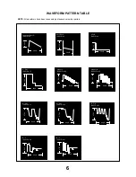
WAVEFORM PATTERN TABLE ...............................................................................................................................................6

ALIGNMENT SETTINGS...........................................................................................................................................................7

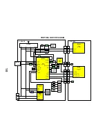
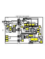
BLOCK DIAGRAMS ..................................................................................................................................................................8

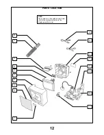
PARTS LOCATION .................................................................................................................................................................12

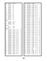
REPLACEMENT PARTS LIST ................................................................................................................................................13

SCHEMATIC DIAGRAMS .......................................................................................................................................................22

CONDUCTOR VIEWS.............................................................................................................................................................25

SAFETY PRECAUTIONS

GENERAL GUIDE LINES

1.  It is advisable to insert an isolation transformer in the

a.c. supply before servicing a hot chassis.

2.  When servicing, observe the original lead dress in the

high voltage circuits. If a short circuit is found, replace
all parts that have been overheated or damaged by
the short circuit.

3.  After servicing, see that all the protective devices

such as insulation barriers, insulation papers, shields
and isolation R-C combinations are correctly
installed.

4.  When the receiver is not being used for a long period

of time, unplug the power cord from the a.c. outlet.

5.  Potentials as high as 20,7kV are present when this

receiver is in operation. Operation of the receiver
without the rear cover involves the danger of a shock
hazard from the receiver power supply. Servicing
should not be attempted by anyone who is not
familiar with the precautions necessary when working
on high voltage equipment. Always discharge the
anode of the tube.

6.  After servicing make the following leakage current

checks to prevent the customer from being exposed
to shock hazard.

LEAKAGE CURRENT COLD CHECK

1.  Unplug the a.c. cord and connect a jumper between

the two prongs of the plug.

2.  Turn on the receiver’s power switch.
3.  Measure the resistance value with an ohmmeter,

between the jumpered a.c. plug and each exposed
metallic cabinet part on the receiver, such as screw
heads, aerials, connectors, control shafts etc. When
the exposed metallic part has a return path to the
chassis, the reading should be between 4M ohm and
20M ohm. When the exposed metal does not have a
return path to the chassis, the reading must be
infinite.

LEAKAGE CURRENT HOT CHECK

1.  Plug the a.c. cord directly into the a.c. outlet. Do not

use an isolation transformer for this check.

2. Connect 

2k

 10W resistor in series with an

exposed metallic part on the receiver and an earth,
such as a water pipe.

3.  Use an a.c. voltmeter with high impedance to

measure the potential across the resistor.

4.  Check each exposed metallic part and check the

voltage at each point.

5.  Reverse the a.c. plug at the outlet and repeat each of

the above measurements.

6.  The potential at any point should not exceed

1,4 Vrms. In case a measurement is outside the limits
specified, there is a possibility of a shock hazard, and
the receiver should be repaired and rechecked before
it is returned to the customer.

X-RADIATION WARNING

1.  The potential sources of X-Radiation in TV sets are

the high voltage section and the picture tube.

2.  When using a picture tube test jig for service, ensure

that the jig is capable of handling 20,7kV without
causing X-Radiation.

NOTE: It is important to use an accurate periodically
calibrated high voltage meter.
1.  Set the brightness to minimum.
2.  Measure the high voltage. The meter should

indicate :-


20kV +0,7kV/-1kV If the meter indication is

out of tolerance, immediate service and correction is
required to prevent the possibility of premature
component failure.

3.  To prevent any X-Radiation possibility, it is essential

to use the specified tube.

HOT CHECK CIRCUIT

A.C. VOLTMETER

WATER PIPE

(EARTH)

TO INSTRUMENT’S EXPOSED
METALLIC PARTS

Fig. 1.

2k

 10 Watts

2

Содержание TX-G10/C

Страница 1: ...d PC to allow a number of diagnostic and control functions to be performed For more details contact your local Panasonic company BACK EXIT TX G10 C Service Manual Safety Specifications Block Diagrams Schematic Diagrams PCB Views Self Check Service Information Parts List Service Hints Disassembly Location of Controls Waveforms Mechanical View Adjustments ...

Страница 2: ...BACK BACK BACK E Schematic Q Schematic Y Schematic E PCB Y PCB Q PCB Audio Power supply Control Video ...

Страница 3: ...HYPERBAND Video Audio Terminals AV1 IN Video 21 pin 1V p p 75Ω Audio 21 pin 500mV rms 10kΩ AV1 IN Front Audio RCAx1 500mV rms10kΩ Video RCAx1 1V p p 75Ω S Video IN Y 1V p p 75Ω 4 pin C 0 3V p p 75Ω AV1 OUT Video 21 pin 1V p p 75Ω Audio 21 pin 500mV rms 1kΩ AV2 IN Audio RCAx1 500mV rms10kΩ Video BNCx1 1V p p 75Ω AV2 OUT Audio Monitor Out Video Monitor Out High Voltage 20kV 0 7kV 1kV Picture Tube A2...

Страница 4: ...rt on the receiver such as screw heads aerials connectors control shafts etc When the exposed metallic part has a return path to the chassis the reading should be between 4M ohm and 20M ohm When the exposed metal does not have a return path to the chassis the reading must be infinite LEAKAGE CURRENT HOT CHECK 1 Plug the a c cord directly into the a c outlet Do not use an isolation transformer for ...

Страница 5: ...over 1 Remove the 7 screws as shown in Fig 2 2 Push clips A and elevate lid 3 Remove the 2 screws as shown in Fig 3 LOCATION OF CONTROLS 3 SCREWS Fig 2 Fig 4 Clips A SCREWS Fig 3 Q Board E Board S 451 Vertical Position Focus Screen Y Board ...

Страница 6: ... as shown in Fig 2 and Fig 3 page3 2 Release chassis from right hand chassis rail and partially withdraw 3 Rotate clockwise the whole T V vertically through 90º 4 After servicing ensure all wiring is returned to its original position before returning the receiver to the customer Fig 5 4 ...

Страница 7: ...irm that TPQ27 measures the same as TPE1 Service Aids To aid in the service of our current chassis there are a number of Service Aids which have been made available LUCI interface kit Linked Utility Computer Interface Part number TZS6EZ002 This contains interface and cables for connecting TV service connector and a PC as well as diagnostic software As new models are introduced upgrade software wil...

Страница 8: ...Pin 43 B Y IC601 Pin 41 64µS 0 7V Vert Drive IC451 Pin 2 20mS 51V Input Vert Out I C IC451 Pin 4 20mS 1 2V VFLB IC451 Pin 3 27V 20mS Video In IC3001 Pin 20 0 9V 64µS H Out IC601 Pin 13 5 2V 64µS Video Out IC3001 Pin 16 2 2V 64µS R Out IC601 Pin 21 64µS 5 75V G Out IC601 Pin 22 5 75V 64µS B Out IC601 Pin 23 5 75V 64µS ...

Страница 9: ...ub Contrast SCon 22 Optimum setting Sub Colour SCol 48 Optimum setting Sub Brightness SBri 49 Optimum setting 1 To place the TV into Service Mode set the Sharpness to minimum position place set in program position 60 press the down button v on the customer controls at the front of the TV and at the same time press the Off Timer button on the remote control 2 Press v v buttons to step up down throu...

Страница 10: ...01 Q3007 Q3006 IC3002 Q3003 Q3001 Q3002 Q3005 IC1201 Red In 15 Green In 11 Blue In 7 Video In 20 EXT In C In 34 TV In Y In 36 B In 25 G In 27 R In 29 B Out 49 G Out 48 R Out 47 CVBS 30 8 B Out 6 G Out 5 R Out 3 B In 2 G In 1 R In 13 R In 12 G In 11 B In 20 TV In 18 EXT Out 16 TV Out C Out 14 AV1 In 10 C In 6 AV2 In 3 JK3003 JK3101 AV1 JK3202 JK3201 Y BOARD E BOARD Q BOARD V Out Y Out 13 CRT Video ...

Страница 11: ... 2 4 IC3003 Q3016 Q3015 Audio Out 1 Audio Out 3 Audio In 2 Audio In 6 FM Out 48 Audio In 47 3 FM In 15 Audio Out JK3101 AV1 E BOARD Q BOARD X103 D101 D102 D103 3 AM In AM FM Out 4 FM AM In 13 12 AV1 In Q3021 Q3020 AV2 In 2 E6 1 Q6 1 JK3201 E10 1 SIF AM JK3003 Audio Video Processor Switching I C Audio Amp ...

Страница 12: ...SDA 6 SCL IC601 14 SDA 11 SCL E15 6 5 TUNER SDA SCL L L Pos Neg 4 CTL 1 16 CTL 2 D103 D101 D104 Q101 Selected Audio To Pin 2 IC601 E7 1 Q7 1 Q3852 21 Coin Det Q304 23 Mute 2 Q253 32 ABL D1401 31 Short D1401 D1401 D1401 D1401 D1401 15V 8V 9V 12V 5V E12 1 Q9 1 E2 8 3 Q2 8 3 2 2 4 T552 AV TV 42 AV2 TV 17 Degauss 5 Q3861 IC3003 11 FM AM or AV1 9 Pos Neg 10 TV AV1 or AV2 Remote Rec Micro Processor Swit...

Страница 13: ... D852 IC852 IC851 IC854 Tuner T552 D456 D553 D554 IC451 IC251 D556 6 4 E9 1 2 Q551 T551 IC602 IC601 Q552 R473 R458 Q501 1 2 1 8 8 K R 1 2 3 4 5 6 7 8 15 13 9 9 16 2 3 8 Vcc 2 11 28 37 1 3 1 3 1 3 1 3 4 5 2 6 3 1 9 19 18 9 20 39 38 13 8 24 3 4 2 3 1 8 7 3 AC In 240V DC In 12 24V 120V 15V 8V 12V 24V 16V 15V 120V 15V 15V 9V 5V 12V 8V 12V 9V 9 7 2 4 6 14 12 5V SBY 5V SBY 9V 33V 5V Micro Processor Remo...

Страница 14: ...PARTS LOCATION 12 NOTE The numbers on the exploded view below refer to the mechanical section of the Replacement Parts List 18 3 9 14 5 1 11 6 7 16 10 8 12 15 13 2 4 17 ...

Страница 15: ... CUSHION BOTTOM TPD8E663 ANTENNA TSA8E006 BATTERY PACK UM 3DJ 2P FIX CLIP MOE2 31221212478 RELAY RL801 TSE1885 1 CRT SOCKET S351 0330660069 TUNER TNR1 TACZ9 021A INSTRUCTION BOOKS GERMAN DUTCH ITALIAN TQB8E2643 2 FRENCH SPANISH SWEDISH TQB8E2717 1 NORG SUOMI DANISH TQB8E2718 1 I C s AUDIO OUTPUT IC251 LA4265 VERTICAL OUTPUT IC451 LA7840 AUDIO VIDEO PROCESSOR IC601 M52779SP DELAY LINE IC602 U3666M ...

Страница 16: ... 17 TRANSISTORS TRANSISTOR Q010 BC847B TRANSISTOR Q101 BC847B TRANSISTOR Q253 BC847B TRANSISTOR Q340 BC847B TRANSISTOR Q351 2SC1473 RN TRANSISTOR Q352 2SC1473 RN TRANSISTOR Q353 2SC1473 RN TRANSISTOR Q354 BC857B TRANSISTOR Q451 BC847B TRANSISTOR Q452 BC847B TRANSISTOR Q501 BC857B TRANSISTOR Q502 BC847B TRANSISTOR Q551 BU2506DFRB TRANSISTOR Q552 2SC3941H TRANSISTOR Q553 BC847B TRANSISTOR Q601 BC857...

Страница 17: ...JA33 ERJ8GEY0R00 125W 5 0 S M CARB JA34 ERJ6GEY0R00 0 1W 5 0 S M CARB JA35 ERJ8GEY0R00 125W 5 0 S M CARB JA36 ERJ8GEY0R00 125W 5 0 S M CARB JA37 ERJ6GEY0R00 0 1W 5 0 S M CARB JA38 ERJ6GEY0R00 0 1W 5 0 S M CARB JA39 ERJ8GEY0R00 125W 5 0 S M CARB JA40 ERJ6GEY0R00 0 1W 5 0 S M CARB JA41 ERJ6GEY0R00 0 1W 5 0 S M CARB JA42 ERJ6GEY0R00 0 1W 5 0 S M CARB JA98 ERJ8GEY0R00 125W 5 0 S M CARB JA99 ERJ6GEY0R0...

Страница 18: ... 5 22K S M CARB R606 ERJ6GEYJ222 0 1W 5 2K2 S M CARB R607 ERJ6GEYJ103 0 1W 5 10K S M CARB R608 ERJ6GEYJ472 0 1W 5 4K7 S M CARB R609 ERJ6GEYJ103 0 1W 5 10K S M CARB R610 ERJ6GEYJ223 0 1W 5 22K S M CARB R611 ERJ6GEYJ475 0 1W 5 4M5 CARBON R802 ERDS1TJ224 0 5W 5 220K CARBON R803 ERDS1TJ224 0 5W 5 220K FUSIBLE R804 ERQ12HJ150 0 1W 5 15 S M CARB R805 ERJ6GEYJ101 0 1W 5 100 WOUND R806 ERW2PKR56 2W 10 R56...

Страница 19: ...RJ6GEYJ750 0 1W 5 75 S M CARB R3015 ERJ6GEYJ750 0 1W 5 75 S M CARB R3016 ERJ6GEYJ750 0 1W 5 75 S M CARB R3017 ERJ6GEYJ221 0 1W 5 220 S M CARB R3018 ERJ6GEYJ181 0 1W 5 180 S M CARB R3020 ERJ6GEYJ470 0 1W 5 47 S M CARB R3021 ERJ6GEYJ104 0 1W 5 100K S M CARB R3022 ERJ6GEYJ104 0 1W 5 100K S M CARB R3023 ERJ6GEYJ102 0 1W 5 1K S M CARB R3024 ERJ6GEYJ562 0 1W 5 5K6 S M CARB R3025 ERJ6GEYJ183 0 1W 5 18K S...

Страница 20: ... 0 5W 5 150 CARBON R3868 ERDS1TJ473 0 5W 5 47K CARBON R3869 ERDS1TJ122 0 5W 5 1K2 CONTROL R3870 EVMEASA00B14 10K SOLID R3871 ERC12GK105D 0 5W 10 1M S M CARB R4001 ERJ6GEYJ681 0 1W 5 680 CAPACITORS ELECT C010 ECA1CM220GB 16V 22µF S M CAP C011 ECUV1H103KBX 50V 10nF S M CAP C012 ECUV1H100CCX 50V 10pF S M CAP C013 ECUV1H100CCX 50V 10pF ELECT C014 ECA1HM101GB 50V 100µF ELECT C017 ECA1HM101GB 50V 100µF ...

Страница 21: ...861 ECA1HM101GB 50V 100µF S M CAP C862 ECUV1H104ZFX 50V 100nF ELECT C863 ECA1HM101GB 50V 100µF S M CAP C864 ECUV1H104ZFX 50V 100nF ELECT C865 ECA1HM101GB 50V 100µF S M CAP C866 ECUV1H104ZFX 50V 100nF ELECT C867 ECA1HM101GB 50V 100µF ELECT C868 ECEA1EGE102 25V 100µF ELECT C869 ECA1EHG102B 25V 100µF ELECT C872 ECA1CM100GB 16V 10µF S M CAP C1201 ECUV1H471JCX 50V 470pF S M CAP C1202 ECUV1H471JCX 50V 4...

Страница 22: ...GB 50V 4 7µF S M CAP C3204 ECUV1H561JCX 50V 560pF FILM C3801 ECQU2A823MNB 200V 82nF FILM C3803 ECQE4225KFB 400V 82nF ELECT C3804 ECA1HM101GB 50V 100µF ELECT C3807 ECEA1HU101 50V 100µF S M CAP C3808 ECUV1H104KBX 50V 100nF ELECT C3810 ECA1VM470B 35V 47µF ELECT C3811 ECEA1HU101 50V 100µF FILM C3850 ECHS1221FZ3 100V 2 2pF ELECT C3852 ECEA1HU101 50V 100µF ELECT C3853 ECA1EM101GB 25V 100µF FILM C3854 EC...

Страница 23: ...NOTES 21 ...

Страница 24: ...and are subject to change without notice REMARKS a Do not touch the hot part or the hot and cold parts at the same time as you are liable to a shock hazard b Do not short circuit the hot and cold circuits as electrical components may be damaged c Do not connect an instrument such as an oscilloscope to the hot and cold circuits simultaneously as this may cause fuse failure Connect the earth of the ...

Страница 25: ......

Страница 26: ......

Страница 27: ......

Страница 28: ...58 D2 TPE35 B5 Q1201 F2 D860 D2 TPE39 A3 Q1202 B4 D861 C2 TPE42 D5 Q1203 B3 D863 E2 TPE43 E6 Q1207 A3 D864 E2 TPE44 E6 Q1208 A3 D867 E2 TPE45 E6 Q1209 B2 D868 D5 TPE50 B7 Q1212 A3 D870 C3 TPE51 B7 Q1213 A4 D871 C3 TPE52 A7 Q1214 A5 D872 C4 TPE53 A7 Q3009 B7 D873 C4 TPE57 C6 Q3010 B7 D874 C4 TPE59 C7 DIODES D875 C4 TPE63 A5 D010 C6 D876 D2 I C s D101 B5 D1201 A4 IC251 C3 D102 B5 D1202 B4 IC451 D6 D...

Страница 29: ...3853 D2 Q3001 D4 D3854 D3 Q3002 D4 D3858 E1 Q3003 D4 D3860 E3 Q3004 D4 D3861 D3 Q3005 D4 D3862 D3 Q3006 C5 TEST POINTS Q3007 D4 TPQ1 D5 Q3008 D4 TPQ2 B4 Q3011 B5 TPQ3 B4 Q3013 C5 TPQ4 B4 Q3014 C5 TPQ5 E4 Q3015 C5 TPQ6 E4 Q3016 C5 TPQ7 E4 Q3017 E5 TPQ8 E5 Q3018 E5 TPQ9 D5 Q3019 D5 TPQ10 E5 Q3020 B4 TPQ11 B5 Q3021 B5 TPQ12 B5 Q3851 C3 TPQ13 B5 Q3852 B3 TPQ14 C4 Q3853 C3 TPQ15 C4 Q3854 C2 TPQ16 D5 Q3...

Страница 30: ...Y BOARD TNP8EY014 DIODES D351 B1 D352 B1 D353 B1 D354 A1 TP S TPY1 A1 TPY2 B2 TPY3 A1 TPY4 B2 TPY5 A2 TPY6 B1 TRAN S Q351 B1 Q352 A1 Q353 B2 Q354 A1 ...

Отзывы: