

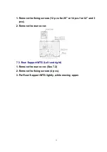
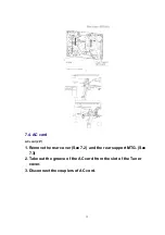
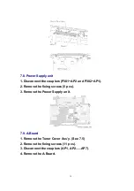


7.8. Power Supply unit
1. Disconnect the couplers (P301~AP2 and P302~AP1).
2. Remove the fixing screws (5 pcs).
3. Remove the Power Supply unit.
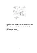
7.9. A-Board
1. Remove the Tuner Cover Ass’y. (See 7.5)
2. Remove the fixing screws (11 pcs).
3. Disconnect the couplers (AP1, AP2......AP7).
4. Remove the A-Board.
16
Содержание TX-32LX60M
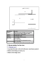
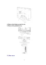
Страница 10: ...4 Remove the fixing screws 4 pcs 5 Remove the pedestal ass y 7 2 Rear cover 10 ...
Страница 24: ...8 Location of Lead Wiring Location of Lead Wiring 26 Location of Lead Wiring 32 24 ...
Страница 25: ...9 EMI Processing EMI Processing 26 EMI Processing 32 25 ...
Страница 27: ...10 3 Option Description 27 ...
Страница 28: ...28 ...
Страница 30: ...11 Adjustment 11 1 Voltage chart of A board 11 2 Voltage chart of AP board 11 3 DVCO adjustment 30 ...
Страница 33: ...32 15 Packing Exploded View 26 33 ...
Страница 34: ...32 34 ...
Страница 35: ...16 Mechanical Replacement Parts List 17 Electrical Replacement Parts List 17 1 Replacement Parts List Notes 35 ...
Страница 36: ...17 2 Electrical Replacement Parts List 18 SCHEMATIC DIAGRAM FOR PRINTING WITH A4 36 ...